Winding mechanism of direct-current motor rotor

A technology of winding mechanism and motor rotor, used in the manufacture of motor generators, electrical components, electromechanical devices, etc., can solve the problems of cumbersome winding process and so on

Active Publication Date: 2014-12-03
NANJING COLLEGE OF INFORMATION TECH
View PDF6 Cites 10 Cited by
  • Summary
  • Abstract
  • Description
  • Claims
  • Application Information

AI Technical Summary

Problems solved by technology

[0003] The purpose of the present invention is to provide a DC motor rotor winding mechanism, which solves the technical

Method used


Image

  • Winding mechanism of direct-current motor rotor
  • Winding mechanism of direct-current motor rotor
  • Winding mechanism of direct-current motor rotor

Examples


Embodiment Construction

[0055] The specific embodiments of the present invention will be further described below in conjunction with the accompanying drawings.

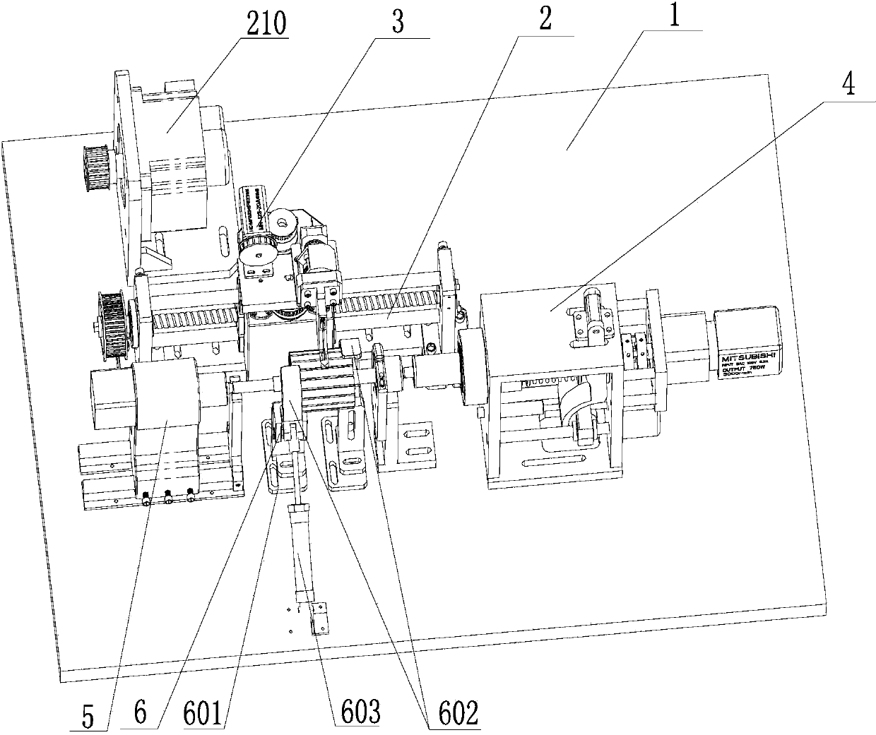
[0056] Such as Figure 1 to Figure 4 The DC motor rotor winding mechanism shown includes a workbench 1, a winding main body mechanism 2, a paint stripping mechanism 3, a clamping mechanism 4 for clamping the motor rotor, and a clamping mechanism 4 that can be positioned on the workbench 1. The tailstock 5 that moves back and forth, the paint stripping mechanism 3 is arranged on the top of the winding body mechanism 2, and the clamping mechanism 4, the tailstock 5 and the winding body mechanism 2 are all arranged on the workbench 1.

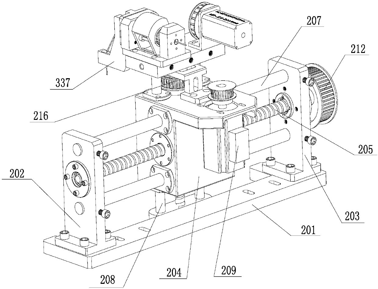
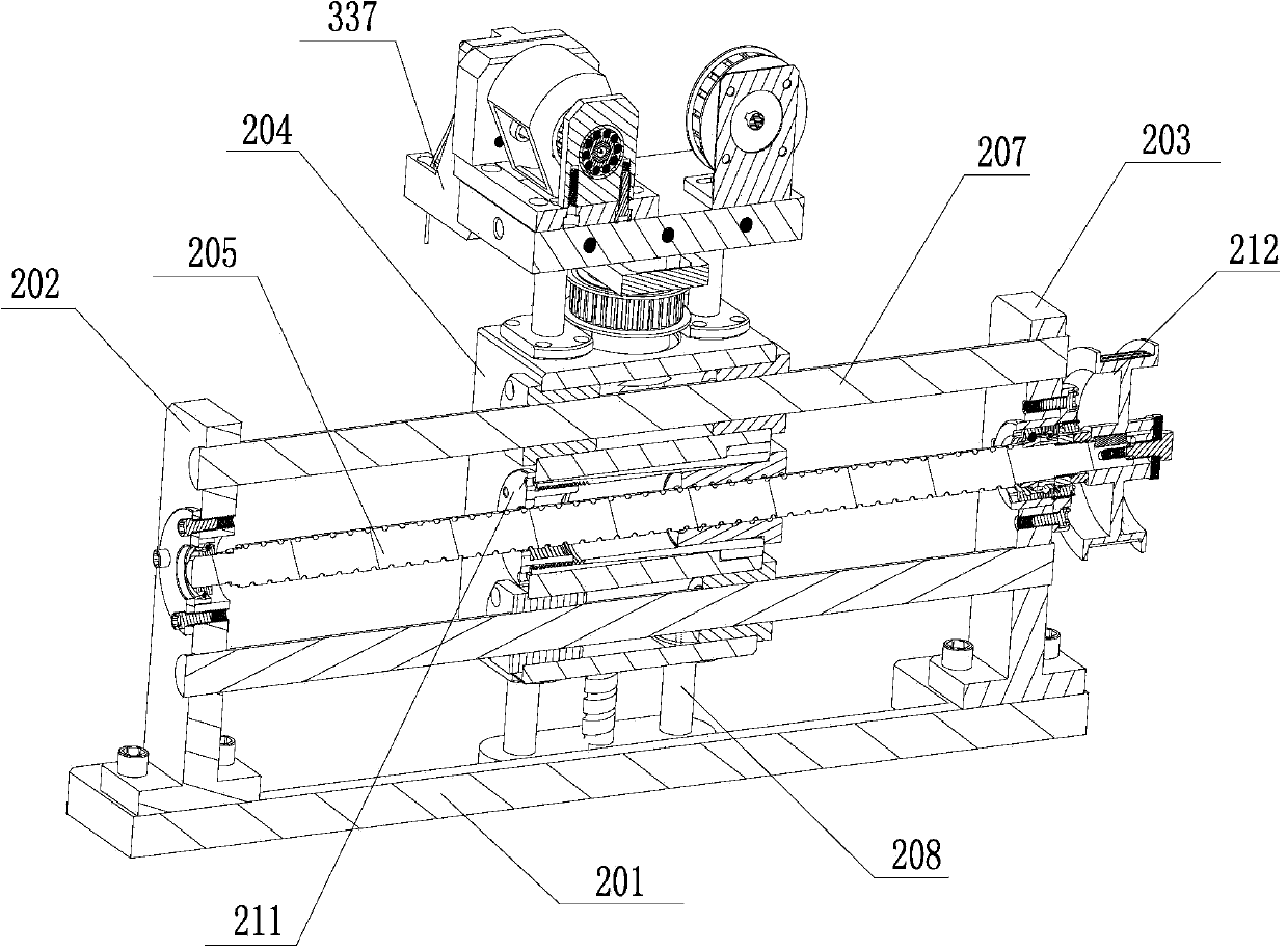
[0057] The winding body mechanism 2 includes a first base 201 arranged on the workbench 1, a first vertical plate 202 and a second vertical plate 203 respectively arranged at both ends of the first base 201, a block 204, and a horizontally arranged first ball Lead screw 205, a vertically arranged second ball sc...


PUM


Abstract

The invention discloses a winding mechanism of a direct-current motor rotor. The winding mechanism comprises a working table, a main winding mechanism, a depainting mechanism, a clamping mechanism used for clamping the motor rotor and a tailstock. The depainting mechanism is arranged at the top of the main winding mechanism, and the clamping mechanism, the tailstock and the main winding mechanism are all arranged on the working platform. The main winding mechanism comprises a first base, a first vertical plate, a second vertical plate, a block, a first lead screw, a second lead screw, one or more first guide rails, one or more second guide rails, a second motor and a first motor, wherein the first vertical plate and the second vertical plate are arranged at the two ends of the first base, the first lead screw is arranged horizontally, the second lead screw is arranged vertically, the first guide rails are arranged horizontally, the second guide rails are arranged vertically, and the first motor is used for driving the first lead screw to rotate. The second lead screw is perpendicular to the first lead screw in different surfaces. The depainting mechanism is arranged on an upper end plate, and the connecting line of the clamping mechanism and the tailstock is parallel to the first lead screw. The winding mechanism has the advantages that the motor rotor does not move axially when the motor rotor conducts winding, the winding process of the motor rotor is simple, and the motor rotor does not need to be positioned repeatedly.

Description

technical field [0001] The invention relates to a DC motor rotor winding mechanism. Background technique [0002] In the production process of the motor rotor, the process of winding the winding on the rotor core usually requires the use of rotor winding equipment. The existing rotor winding equipment is generally equipped with a rotor winding mold, a winding mechanism, and an indexing mechanism for installing the rotor core. ;The winding mechanism is fixed. When winding, the motor rotor is moved back and forth. First, the motor rotor is positioned, and then the motor rotor is reciprocated to wind the first set of coils. An angle, then position the motor rotor, and then move the motor rotor back and forth to wind the second set of coils. During the whole process, the motor rotor is constantly reciprocating, so it must be positioned before winding each set of coils. The winding process is very fast. is cumbersome. Contents of the invention [0003] The purpose of the pres...

Claims


Application Information

Patent Timeline
IPC IPC(8): H02K15/08
Inventor 刘晓强张凯朱方圆章艳周召信
Owner NANJING COLLEGE OF INFORMATION TECH
Why Eureka
Try Eureka