
Scalding pool for pig slaughtering

A conveying rail and pulley technology, applied in the field of slaughtering, can solve the problems of unfavorable and flexible arrangement of slaughter lines, running line length, carcass decoupling, etc., and achieves the effects of not easy decoupling, reducing steam waste, and flexible arrangement

Inactive Publication Date: 2014-12-10
SHANXI TIANPENG AGRI & ANIMAL HUSBANDRY
View PDF0 Cites 3 Cited by
  • Summary
  • Abstract
  • Description
  • Claims
  • Application Information

AI Technical Summary

Problems solved by technology

[0003] The present invention aims at the problems of the above-mentioned products, and provides a pig scalding pool for slaughtering pigs, which solves the problem that most of the existing hot water scalding pools in the above-mentioned products are mostly open, and the boiling scalding pool has a large amount of steam. Pond 4 will waste this heat energy. The pigs will be tilted due to the direction of water flow in the scalding pool, which will easily cause the carcass to be unhooked. Moreover, the running line of the pig body from one end of the scalding pool to the other end is longer , the running line in the scalding pool is often used as a part of the continuous connection of the entire slaughtering line. When it is necessary to modify the slaughtering line, it will cost a lot, which is not conducive to the flexible arrangement of the slaughtering line and other issues.

Method used


Image

  • Scalding pool for pig slaughtering
  • Scalding pool for pig slaughtering

Examples


Embodiment Construction

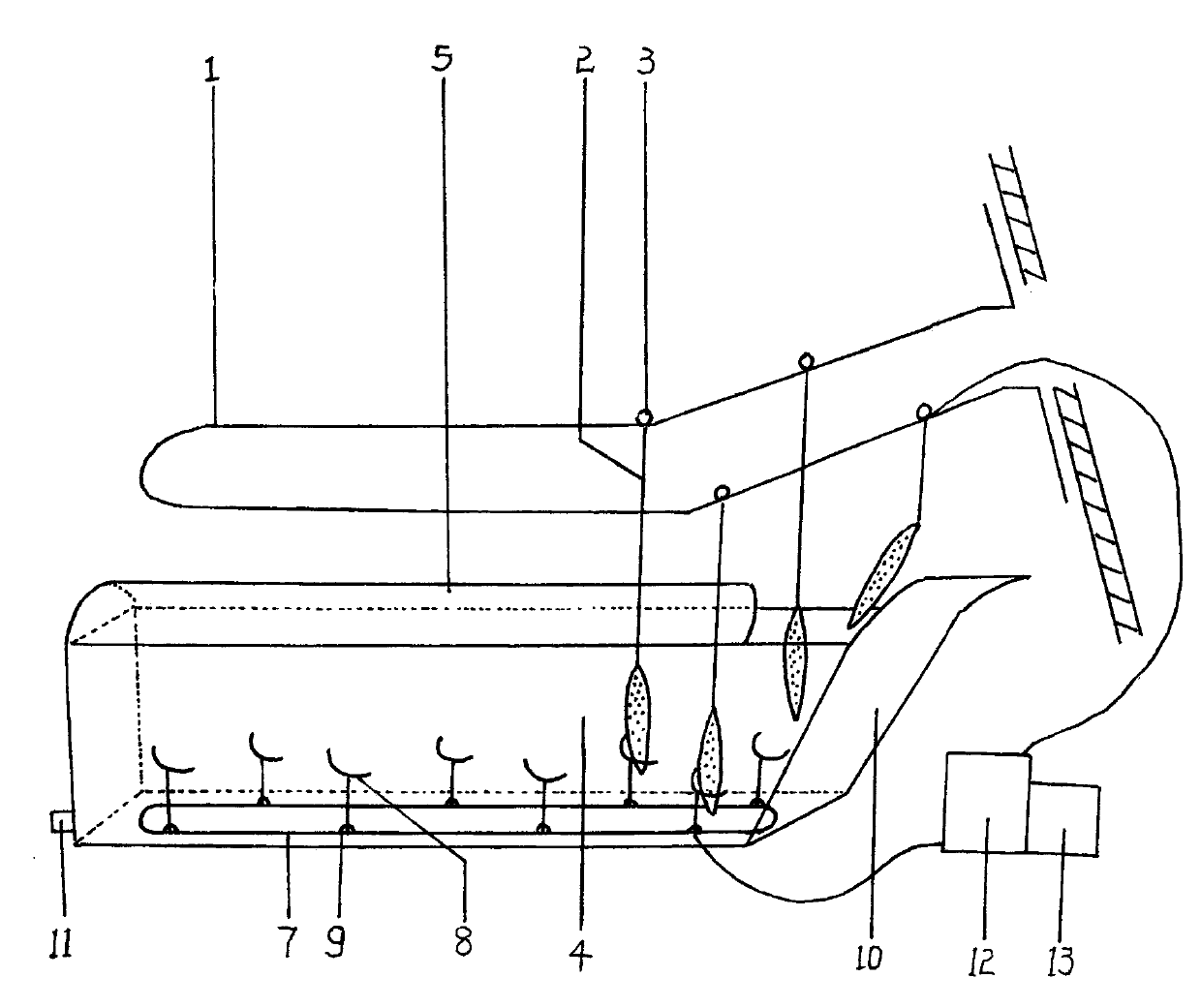
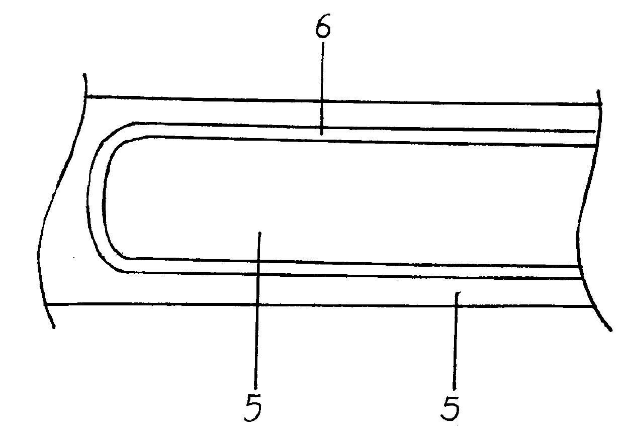
[0009] A scalding pool for slaughter pigs, comprising a conveyor rail 1, a hanging chain 2, an upper pulley 3, a scalding pool 4, a top cover 5, a hollow groove 6, an annular conveying rail 7, a limit frame 8, a lower wheel 9, and a slope surface 10. Drainage port 11, motor 12, reducer 13, there are several hanging chains 2 under the conveying rail 1, and the top of the hanging chain 2 is provided with an upper pulley 3 that can slide on the conveying rail 1. The top cover 5 of the scalding pool 4 is provided with a hollow groove 6 that matches the running track of the conveying rail 1. A slope surface 10 is provided on the side of the pig body entrance of the scalding pool 4 for the pigs on the lifting chain 2. The body slowly enters the ironing pool 4 to reduce the impact force on the water of the ironing pool 4 when it falls. The bottom of the ironing pool 4 is provided with a drainage port 11 and an annular conveying rail 7. There are several limit racks 8 on the annular con...


PUM


Abstract

The invention discloses a scalding pool for pig slaughtering. The scalding pool comprises a conveying rail, hanging chains, upper pulleys, a scalding pool body, a top cover, a hollowed groove, an annular conveying rail, limiting racks, lower pulleys, a slope, a drain outlet, a motor and a speed reducer. A plurality of hanging chains are arranged at the bottom of the conveying rail, the upper pulleys which can slide on the conveying rail are arranged at the top ends of the hanging chains, the scalding pool body is arranged below the conveying rail, the hollowed groove matched with the operation track of the conveying rail is formed in the top cover of the scalding pool, the slope is arranged on one side of the scalding pool body, the drain outlet and the annular conveying rail are arranged at the bottom of the scalding pool body, a plurality of limiting racks are arranged on the annular conveying rail, arc clamping-opening-shaped frames are arranged on the upper portions of the limiting racks, the lower pulleys are arranged at the bottoms of the limiting racks, and an external drive system composed of the motor and the speed reducer is used for controlling the operation speed of the upper pulleys and the operation speed of the lower pulleys, so that the operation speed of the upper pulleys and the operation speed of the lower pulleys are matched, and pigs are right clamped in appropriate limiting racks when the pigs fall down. Steam is used for increasing heat energy in the scalding pool, the pigs in the scalding pool can not be easily separated from hooks, and the operation line of the pigs in the scalding pool is short.

Description

Technical field [0001] The invention relates to the field of slaughter, in particular to a scalding pool for slaughtered pigs. Background technique [0002] In the process of slaughter and processing of pigs, hot water is needed to scald the pigs. Most of the existing hot water scalding pools are canal type, which uses a conveyor mechanism to drive the pigs under the traction of the pig carcass under the controllable lifting rail. Keep hanging in the scalding pool, and then lift it to the pig dropping device in front of the dehairing machine after the scalding. The entire scalding process does not require manual operation and basically realizes the mechanized processing of the production line. However, the mouth of this hot water scalding pool is mostly open. The boiling scalding pool has a lot of steam. The open scalding pool will waste this heat. The pigs’ body position will be tilted due to the direction of the water flow in the scalding pool. It is easy to decouple the carca...

Claims


Application Information

Patent Timeline
Patent Type & Authority Applications(China)
IPC IPC(8): A22B5/08
Inventor 蒋月斌姚志刚
Owner SHANXI TIANPENG AGRI & ANIMAL HUSBANDRY
Learn More