Glass gas-liquid separator

A gas-liquid separator and glass technology, which is applied in laboratory utensils, laboratory containers, chemical instruments and methods, etc. The effect of good separation and simple structure

Active Publication Date: 2014-12-10
安徽圣达生物药业有限公司
View PDF5 Cites 0 Cited by
  • Summary
  • Abstract
  • Description
  • Claims
  • Application Information

AI Technical Summary

Problems solved by technology

[0002] The gas-liquid separation method using heating distillation is a common method for purifying liquid substances at present. For example, Chinese Patent Publication No. CN202983717U discloses "A Liquid Separation Instrument and Liquid Separation Device". The connecting pipe connected to the lower part of the chamber and the interface connected to the upper part of the liquid storage chamber, wherein the position where the liquid storage chamber is connected to the connecting pipe is provided with a first two-way piston, and the liquid separation instrument also includes a communication port A side pipe and a liquid branch pipe, the upper interface of the communication side pipe is located on the side wall of the upper part of the liquid storage chamber, the lower interface of the communication side pipe is located on the side wall of the connecting pipe, and the liquid storage chamber and The connecting pipe is connected through the connecting side pipe, and the second two-way piston is arranged on the liquid separating branch pipe. The disadvantages are: firstly, the structure is complex and the production cost is high; secondly, the condensed liquid When returning to the liquid storage chamber, it will be mixed with the steam from the connecting side pipe. After mixing, part of the condensed liquid will carry the steam into the bottom of the liquid storage chamber, and part of the steam will carry the liquid into the condensation pipe, causing the work burden of the condensation pipe.

Method used


Image

  • Glass gas-liquid separator

Examples


Embodiment Construction

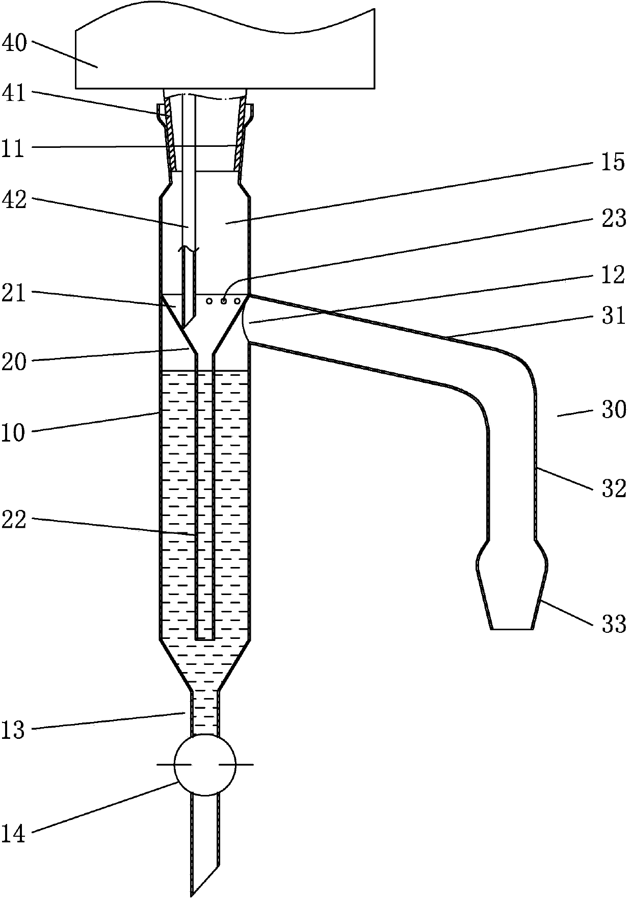
[0018] Below in conjunction with accompanying drawing, the present invention will be further described with specific embodiment, see figure 1 :

[0019] Gas-liquid separator made of glass, the upper side of the tube body 10 is provided with an inner frosted interface 11, the lower side of the tube body 10 is provided with a constricted part 13, and a valve 14 is arranged on the constricted part 13, and the middle and upper part of the inner cavity of the tube 15 An infusion funnel 20 with a large top and a small bottom is provided, and the upper end periphery of the infusion funnel 20 is connected with the inner wall of the tube body 10, and an opening 12 is arranged on the inner wall of the tube body 10 at the lower side of the junction of the infusion funnel 20 and the tube body 10, and the opening 12 is connected with a branch pipe 30 communicating with the inner cavity 15 of the tube, and the outer end of the branch pipe 30 is provided with an external frosted interface 33...


PUM


Abstract

The invention belongs to the technical field of gas-liquid separation and discloses a glass gas-liquid separator. An inner dull polish connector is arranged on the upper side of a pipe body; a necking part is arranged on the lower side of the pipe body; a valve is arranged on the necking part; a liquid delivery funnel with large top and small bottom is arranged on the middle upper part of an inner cavity of the pipe body; the periphery of the upper end of the liquid delivery funnel is connected with the inner wall of the pipe body; an opening is formed in the side wall of the pipe body on the lower side of the joint of the liquid delivery funnel and the pipe body; a branch pipe communicated with the inner cavity of the pipe body is connected to the opening; an outer dull polish connector which is conveniently connected with a flask is arranged at the outer end of the branch pipe; and multiple air holes are peripherally formed in the side wall of the liquid delivery funnel close to the lower side of the joint of the liquid delivery funnel and the pipe body at intervals. The glass gas-liquid separator has the advantages of simple structure, low production cost, good gas-liquid separation effect and applicability to serve as a gas-liquid separation device.

Description

technical field [0001] The invention belongs to the technical field of gas-liquid separation and specifically designs a gas-liquid separator made of glass. Background technique [0002] The gas-liquid separation method using heating distillation is a common method for purifying liquid substances at present. For example, Chinese Patent Publication No. CN202983717U discloses "A Liquid Separation Instrument and Liquid Separation Device". The connecting pipe connected to the lower part of the chamber and the interface connected to the upper part of the liquid storage chamber, wherein the position where the liquid storage chamber is connected to the connecting pipe is provided with a first two-way piston, and the liquid separation instrument also includes a communication port A side pipe and a liquid branch pipe, the upper interface of the communication side pipe is located on the side wall of the upper part of the liquid storage chamber, the lower interface of the communication ...

Claims


Application Information

Patent Timeline
Patent Type & Authority Applications(China)
IPC IPC(8): B01L3/16
Inventor 褚定顺王文初朱勇刚陈伶利朱亦恒
Owner 安徽圣达生物药业有限公司
Why Eureka
Try Eureka