
A tool setting device and method for CNC lathe based on machine vision

A CNC lathe and machine vision technology, applied in auxiliary devices, turning equipment, accessories of tool holders, etc., can solve the problems of high technical level and work emotion dependence, low tool setting accuracy, and high cost, and avoid unnecessary loss, high work efficiency, and the effect of preventing accidents

Inactive Publication Date: 2016-06-08
KUNMING UNIV
View PDF5 Cites 4 Cited by
  • Summary
  • Abstract
  • Description
  • Claims
  • Application Information

AI Technical Summary

Problems solved by technology

In contrast, the trial cutting method does not require auxiliary equipment for tool setting. The method is simple, but it takes a long time. It depends heavily on the operator's technical level and work mood, and the accuracy of tool setting is not high; special tool setting instrument and automatic tool setting Tool setting can achieve higher tool setting efficiency and accuracy, but the cost is too high, and a certain amount of downtime or machine adjustment time is still required, which limits the fast and efficient function of CNC lathes. Therefore, a new tool setting method is needed method is born

Method used


Image

  • A tool setting device and method for CNC lathe based on machine vision
  • A tool setting device and method for CNC lathe based on machine vision
  • A tool setting device and method for CNC lathe based on machine vision

Examples


Embodiment 1

[0040] Such as Figure 7 Shown: During the machining process, install a turning tool detection camera 5 in an open area that does not interfere with the workpiece fixture on the CNC lathe, which can be used to detect the wear and damage of the turning tool, as well as the tool offset value of the replaced tool during the machining process Determination. Turning tool detection camera 5 is installed in the rear top in the nacelle. Install the turning tool detection camera 5 according to the aforementioned method and perform dimensional accuracy calibration on the turning tool detection camera 5 .

[0041] Before the processing starts, the program can be used to control the movement of each tool including the reference tool into the field of view of the turning tool detection camera 5, collect the initial digital image of each tool, and record information such as mechanical coordinates; Control the moving tool to enter the field of view of the turning tool detection camera 5, c...


PUM


Abstract

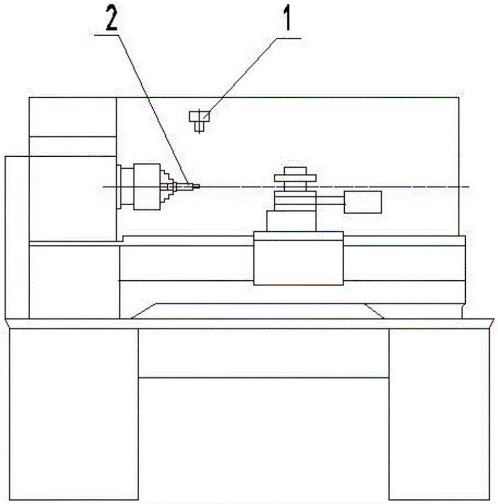
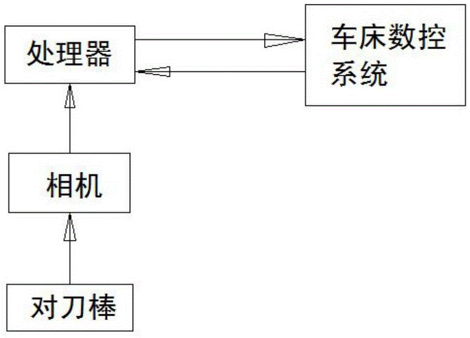
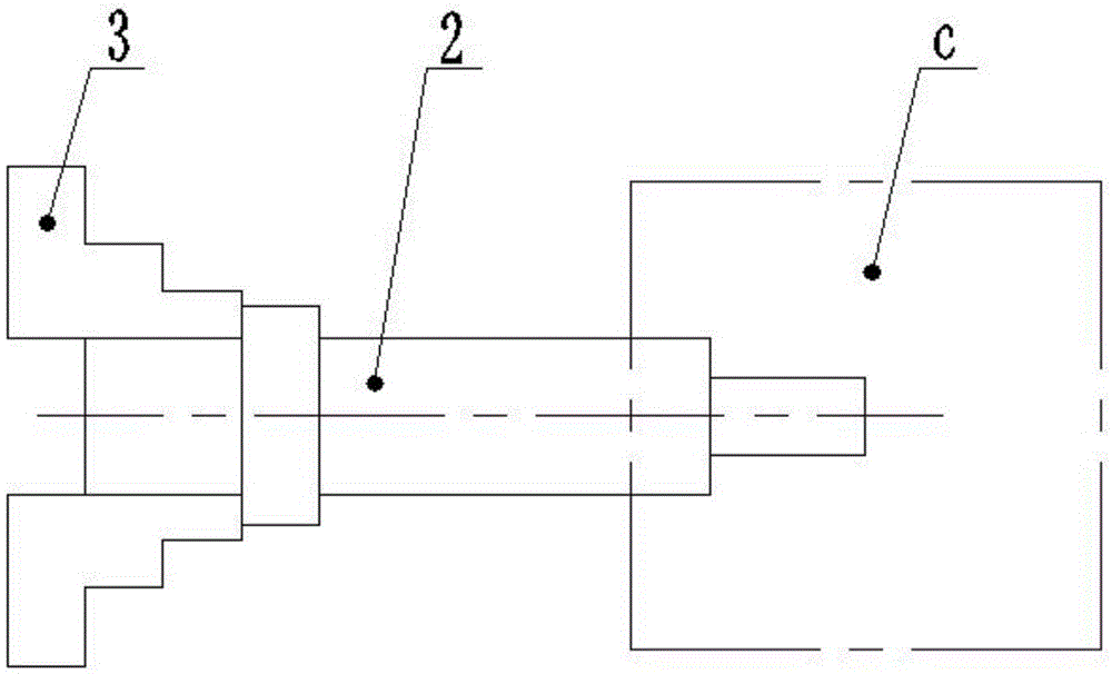
The invention discloses a device and a method of tool setting of a digital controlled lathe based on machine vision. The device comprises a tool setting bar, a camera and a processor. The tool setting bar is arranged on a chuck of the lathe, the camera is fixedly arranged above a hatch door in the lathe and above the tool setting bar, the lens of the camera points at the front end of the tool setting bar, and the view-field horizontal direction of the camera installation angle overlaps with the axis of the tool setting bar. The signal output end of the camera is connected with a digital control system of the lathe through the processor. Digital images of turning tools arranged on the digital controlled lathe are collected by the camera and transferred to the processor which identifies tip points of the turning tools and then writes the calculated tool deviation value into the digital control system of the lathe. No trial cut or contact measurement is needed, and tool setting can be completed quickly. Additionally, abrasion and damage of the tools can be monitored, so that tool abrasion can be compensated and tool damage can be alarmed, thereby reducing accidents and unnecessary losses. The device of the tool setting of the digital controlled lathe based on the machine vision is convenient to use, high in work efficiency and widely applicable.

Description

technical field [0001] The invention relates to a numerically controlled lathe processing technology, in particular to a tool setting device and a tool setting method for a numerically controlled lathe based on machine vision. Background technique [0002] Tool setting is one of the more complicated process preparations in CNC lathe machining. The accuracy of tool setting will directly affect the programming of machining programs and the machining accuracy of parts. At the same time, the efficiency of tool setting will directly affect the machining efficiency of CNC lathe. Due to the different types of tools and the randomness of installation, the positions of the tool positions of each tool in the machine tool coordinate system are different. If the tool used in the zero calibration operation is used as the reference tool, other tools will There is a relative position deviation between the points, which is the so-called tool offset value. One of the main tasks of the tool s...

Claims


Application Information

Patent Timeline
Patent Type & Authority Patents(China)
IPC IPC(8): B23B25/06
CPCB23B25/06
Inventor 安宇陈为民王玮栗勋
Owner KUNMING UNIV
Learn More