On-line monitoring method for cutter abrasion damage based on main shaft driving current and working step.

A technology of spindle drive and tool wear, which is applied in the field of on-line monitoring of tool wear and damage of CNC machine tools and on-line monitoring of tool wear and damage. It can solve problems such as changing machine tools, affecting normal processing, and poor applicability, so as to reduce tool use costs and workpieces. Scrap rate and machine tool failure rate, effect of improving service life

Active Publication Date: 2019-06-21
BEIJING UNIV OF TECH +1
View PDF15 Cites 20 Cited by
  • Summary
  • Abstract
  • Description
  • Claims
  • Application Information

AI Technical Summary

Problems solved by technology

The direct measurement method is used to measure the appearance and geometric dimensions of the blade, but it needs to be stopped for detection and takes up public hours. According to industrial statistics, the resulting downtime accounts for about 20% to 30% of the total downtime of the machine tool; the indirect measurement method mostly uses the installation of sensors. Monitor the characteristic signal, but the installation and use of the sensor will affect the normal processing and even need to change the structure of the machine tool, mostly used to verify the theoretical research
Scholars at home and abroad have made remarkable achievements in the field of on-line monitoring of tool wear, but there are still some problems in the actual production process. Poor applicability of factors

Method used


Image

  • On-line monitoring method for cutter abrasion damage based on main shaft driving current and working step.
  • On-line monitoring method for cutter abrasion damage based on main shaft driving current and working step.
  • On-line monitoring method for cutter abrasion damage based on main shaft driving current and working step.

Examples


Embodiment Construction

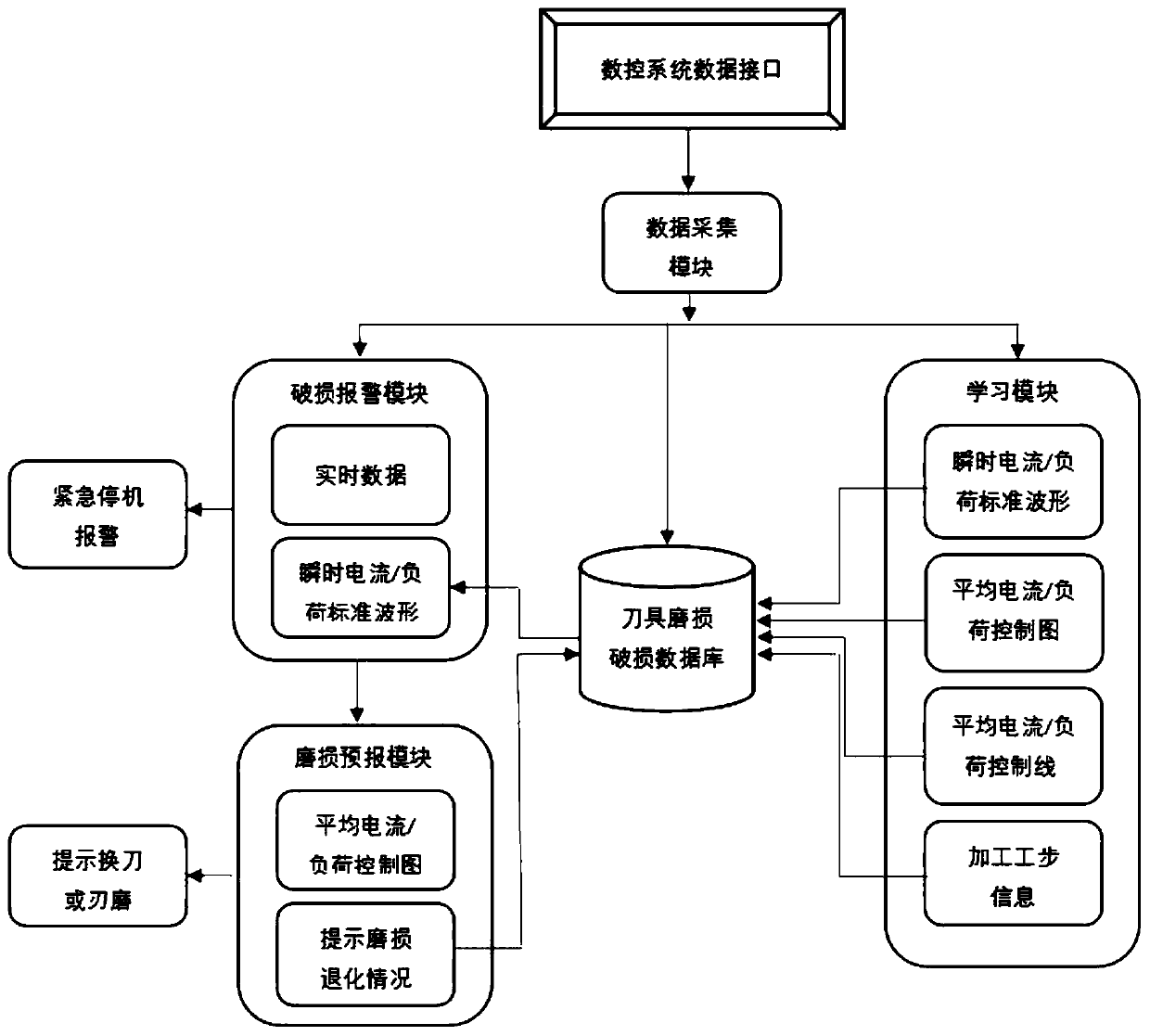
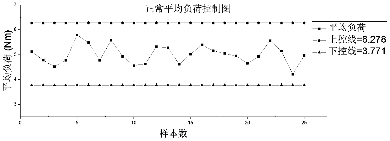
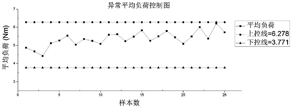
[0019] The monitoring system provided by the present invention obtains the spindle drive current / load and processing step information through the data interface of the numerical control system, and after averaging and eliminating random errors, it fits the standard waveform curve of the instantaneous current / load changing with the processing time during the normal processing of the working step . During the machining process of CNC machine tools, the instantaneous current / load is monitored and compared with the standard curve. When it is judged that the tool is damaged, an alarm signal is sent to trigger the emergency shutdown protection of the machine tool. In addition, after the machining of the workpiece, create an average current / load average control chart and analyze the wear state of the tool, and dynamically adjust the tool change or sharpening rules of the machining tool.

[0020] The on-line monitoring method of tool wear and damage based on spindle drive current and ...


PUM


Abstract

The invention discloses an on-line monitoring method for cutter abrasion damage based on main shaft driving current and working step. The method is made by the following steps that realizing communication with a numerical control system to obtain machining working step information, meanwhile, the driving current and the load of the main shaft are monitored, and on the basis of a normal cutter andabrasion damage cutter cutting torque difference analysis and statistical quality control principle. Control graph for drawing average current / load required by each working step processing, a control graph control line is reasonably formulated, the abrasion state of each working step is judged, and a tool changing or cutter edge grinding rule is formulated. According to the variation of instantaneous main shaft current or instantaneous load with the deviation from the instantaneous current / load in normal machining in each working step of machining, the cutter breakage is determined, the alarm signal is sent to inform the numerical control system to emergency shutdown so as to avoid the serious consequences of damaging the workpiece and the machine tool. According to the method, on onehand, the part rejection rate and the machine tool fault rate can be reduced, on the other hand, the service life of the cutter can be prolonged to the maximum extent, and the use cost of a plant cutter is reduced.

Description

technical field [0001] The invention relates to a method and device for on-line monitoring the wear and damage state of CNC machine tool tools, in particular to an online monitoring method for tool wear and damage based on the drive current of the spindle of the CNC machine tool and the information of workpiece processing steps, and belongs to the technical field of state monitoring of CNC machine tools. Background technique [0002] With the continuous development of intelligent manufacturing technology, the degree of automation of the manufacturing system is getting higher and higher, and the production process tends to be unattended, especially in the actual production process, the tool is frequently used and worn during the cutting process for a long time. Tool wear and damage is the most common phenomenon in the machining and manufacturing process. The light ones lead to the scrapping of the workpiece, and the severe ones lead to serious consequences such as knife sticki...

Claims


Application Information

Patent Timeline
Patent Type & Authority Applications(China)
IPC IPC(8): B23Q17/09
Inventor 王民宋铠钰朱葛龙程大勇
Owner BEIJING UNIV OF TECH
Why Eureka
Try Eureka