Position-adjustable elevator vertical expansion device with avoiding space

A technology for avoiding space and tensioning devices, which is applied in transportation, packaging, elevators, etc., can solve the problems of large space occupied by tensioning devices, increase the cost of elevator use, and limit the use of elevators, so as to improve installation efficiency, occupy small space, and The effect of low cost of use

Active Publication Date: 2014-12-10
HEBEI DONGFANG FUDA MACHINERY
View PDF9 Cites 0 Cited by
  • Summary
  • Abstract
  • Description
  • Claims
  • Application Information

AI Technical Summary

Problems solved by technology

However, the position of the tensioning device cannot be adjusted at will. When the tensioning device of the elevator is far away from the guide rail or is higher than the ground, it is necessary to use auxiliary equipment, such as extending the cantilever or adding a base between the tensioning device and the ground.
The addition of equipment not only greatly increases the cost of elevator use, but also makes the structure of the tensioning device complicated, and also increases the difficulty of installation and layout.
In addition, after adding equipment, the tensioning device takes up a lot of space, which is not suitable for the case of small pits, which brings great restrictions on the use of elevators
In addition, due to the need to add equipment according to the conditions, the size of the hoistway space is different, and the distance between the installation position of the speed limiter and the guide rail is different, so the tensioning device cannot be standardized.
All of the above have brought great inconvenience to the use and installation of the elevator.

Method used


Image

  • Position-adjustable elevator vertical expansion device with avoiding space
  • Position-adjustable elevator vertical expansion device with avoiding space
  • Position-adjustable elevator vertical expansion device with avoiding space

Examples


Embodiment Construction

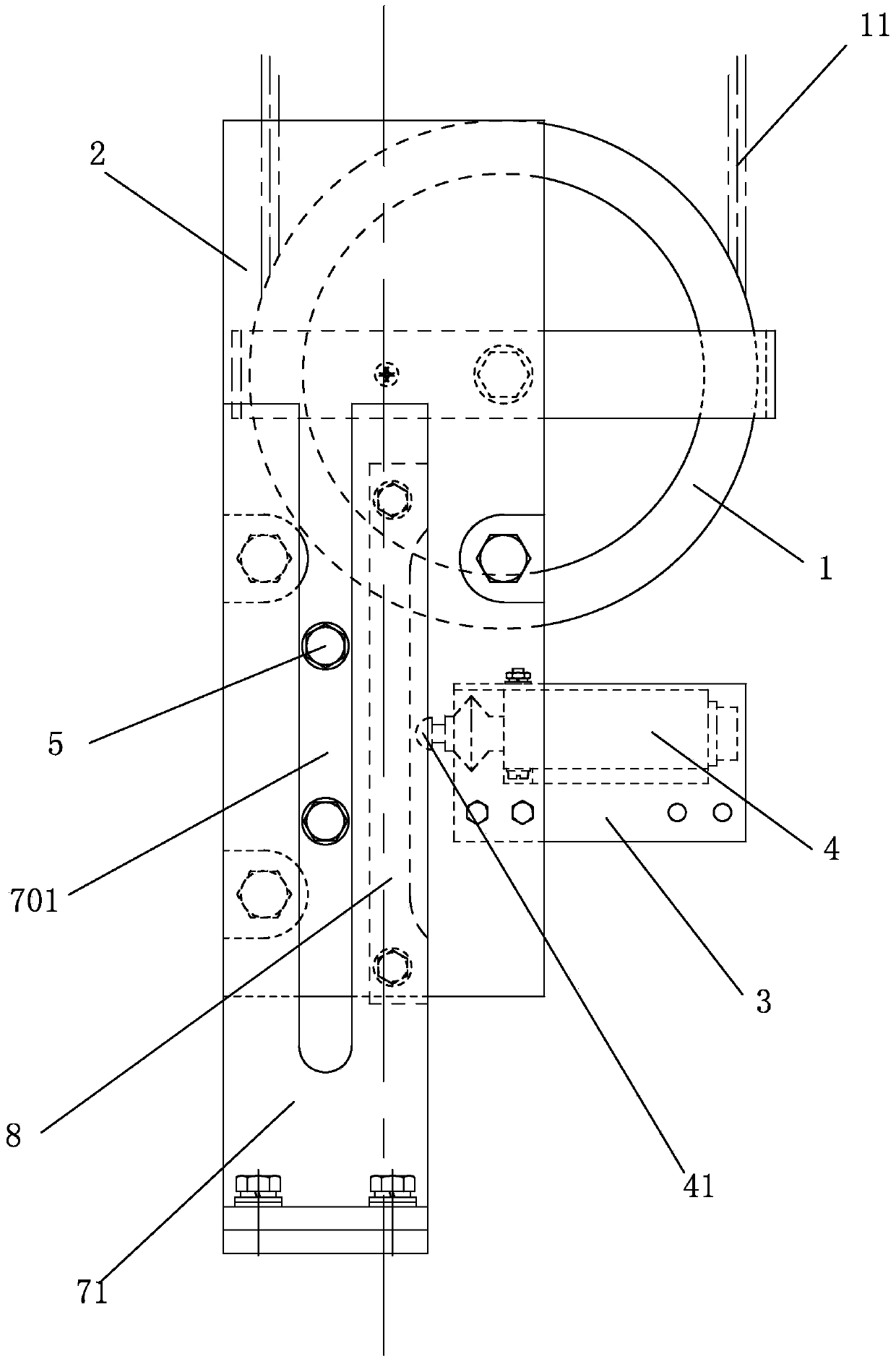
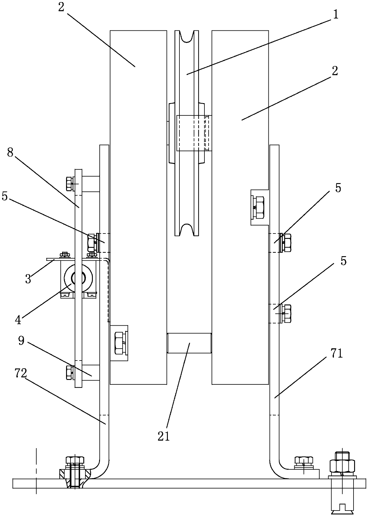
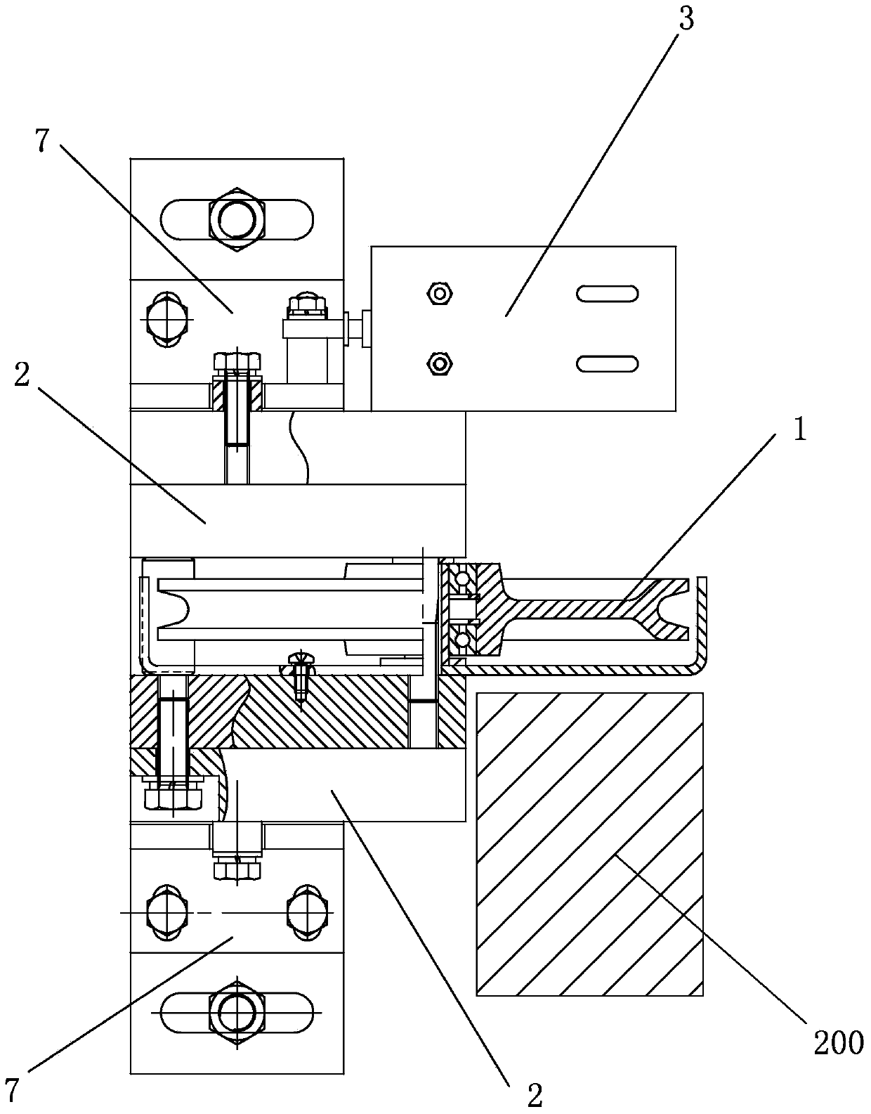
[0022] Such as figure 1 As shown, the elevator vertical tensioning device with adjustable position and avoidance space of the present invention includes a weight part, a bracket part, and a combination Figure 4 , Figure 5 As shown, the weight part includes two weights 2 symmetrically arranged front and back, a sheave 1 is installed between the two weights 2, a steel wire rope 11 is wound on the sheave 1, the sheave of the sheave 1 and the weight 2 Arranged in parallel front and back, the middle of the two weights 2 is provided with a threaded hole, the threaded shaft 6 passes through the threaded hole and the center of the rope wheel 1 from back to front, and the rope wheel 1 is installed between the two weights 2, and the two The bottom ends of each weight 2 are fixedly connected together. recombine figure 2 As shown, the bottom ends of the two weights 2 can be fixed by bolts and spacer connecting columns 21 between the weights, so that there is a space between the two ...


PUM


Abstract

The invention relates to a position-adjustable elevator vertical expansion device with an avoiding space. The position-adjustable elevator vertical expansion device comprises a hammer part and a support part. The hammer part comprises heavy blocks which are symmetrical front and back and a rope wheel between the heavy blocks. A steel wire rope is wound on the rope wheel. A switch is fixed on a back heavy block. A switch contact extends leftwards. Guiding columns are arranged on the heavy blocks. The guiding columns are placed in guiding grooves in the support part and can slide up and down along the guiding grooves. The support part comprises a switch striking plate which is vertically placed. The middle portion of the surface of the right side of the switch striking plate is a plane. The upper portion and the lower portion of the surface of the right side of the switch striking plate are concave arc faces. The switch contact moves in the length range d of the surface of the right side. The elevator vertical expansion device is convenient to operate, the position can be adjusted freely, auxiliary equipment does not need to be added, the structure is simple, occupied space is small, using cost is low, and shaftways of different sizes can be subjected to standard mounting.

Description

technical field [0001] The invention relates to the application technical field of detecting, fault correcting or safety devices in elevators responding to abnormal operating conditions, in particular to an elevator vertical tensioning device with adjustable position and space for avoidance. Background technique [0002] In the actual application of the elevator, the commonly used cantilever tensioning device includes a cantilever protruding from the guide rail, a mounting arm rotatably arranged on the cantilever, a sheave assembly mounted on the heavy block. When the wire rope is extended, under the gravity of the weight, the installation arm rotates downward relative to the cantilever, and moves downward with the sheave assembly and the weight to tension the wire rope. But the position of this tensioning device can not be adjusted arbitrarily, when the elevator tensioning device is far away from the guide rail or when it is higher from the ground, it is necessary to use a...

Claims


Application Information

Patent Timeline
Patent Type & Authority Applications(China)
IPC IPC(8): B66B7/10
Inventor 海立冬贾砚华周军然孙雪松王晓会
Owner HEBEI DONGFANG FUDA MACHINERY
Why Eureka
Try Eureka