Construction method for cast-in-situ hollow floorslab and airbag-type core framework thereof

A technology of hollow floor slab and construction method, which is applied in the direction of floor slabs, building components, buildings, etc., and can solve the problems that the airbag is easy to form a curved surface, it is difficult to form a chamfer, and the airbag mandrel is easy to warp, etc.

Active Publication Date: 2014-12-10
广东班高得绿色建工科技有限公司
View PDF9 Cites 5 Cited by
  • Summary
  • Abstract
  • Description
  • Claims
  • Application Information

AI Technical Summary

Problems solved by technology

[0005] In addition, in order to form a guiding effect on the poured concrete and make the concrete pouring smoother, chamfers are provided on the existing mandrel. For example, in the application number 201310564664.6, the application date is November 14, 2013 and the publication date is 2014. The patent document on February 5 discloses a mandrel, which is composed of a foamed inner core and a protective layer wrapped on the foamed inner core. Since the mandrel is mainly a foamed inner core, it is inverted Corners are easy to form during the foaming process. Of course, chamfers can also be formed by cutting, but for the air bag mandrel, once inflated, the air bag is easy to form an arc surface under the action of gas and it is difficult to form chamfers. cannot achieve the above purpose
[0006] In the prior art, a method for fixing the foam mandrel is also disclosed. The method is to fix the foam mandrel with criss-cross straps. Structurally fixed airbag mandrels are prone to warping

Method used


Image

  • Construction method for cast-in-situ hollow floorslab and airbag-type core framework thereof
  • Construction method for cast-in-situ hollow floorslab and airbag-type core framework thereof
  • Construction method for cast-in-situ hollow floorslab and airbag-type core framework thereof

Examples


Embodiment Construction

[0059] The present invention will be further described in detail below in conjunction with the accompanying drawings and specific embodiments.

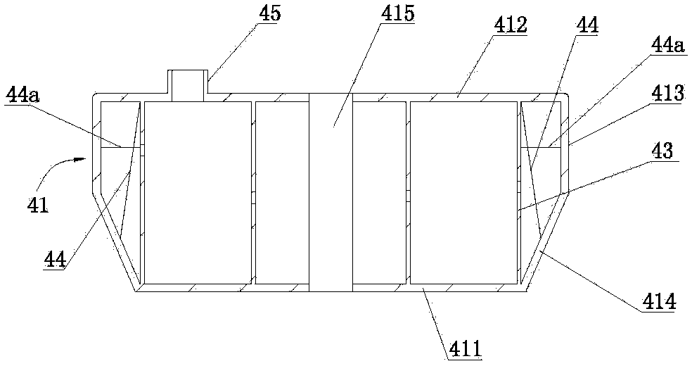
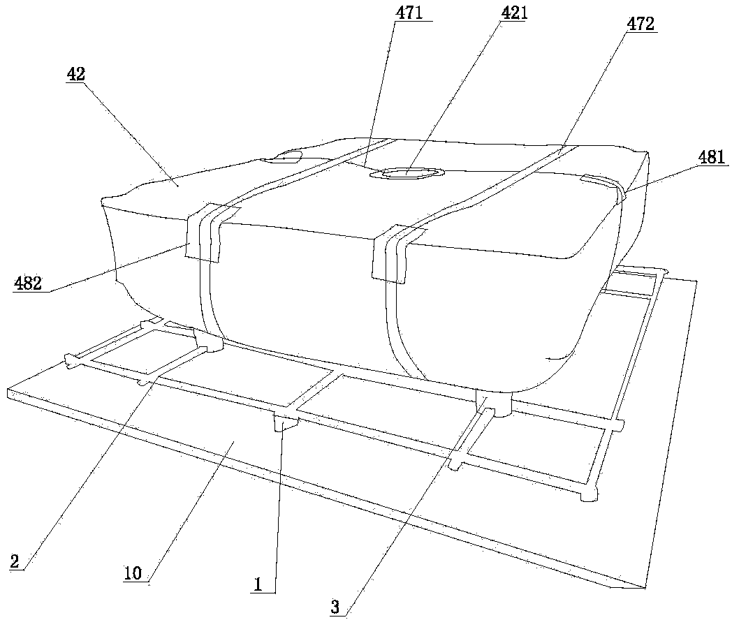
[0060] Such as figure 1 with figure 2 As shown, the airbag type mandrel of the cast-in-place hollow floor slab includes an airbag bag 41 and a protective layer 42 covering the airbag bag 41 .

[0061] A through hole 415 is opened in the middle of the airbag bag 41 for installing and fixing the protection device. In this embodiment, the cross section of the airbag bag 41 is square. The airbag bag 41 includes a bottom surface 411, a top surface 412, a side surface 413 and a transition slope 414; the upper edge of the side surface 413 is connected to the edge of the top surface 412 by welding, and the lower edge of the side surface 413 is connected to the transition surface by welding. on the upper edge of the bevel 414. The lower edge of the transition bevel 414 is connected to the edge of the bottom surface 411 by welding, and the ...


PUM


Abstract

The invention discloses a construction method of a cast-in-situ hollow floorslab and an airbag-type core framework thereof. The airbag-type core framework comprises an airbag cover and a protecting layer sleeving outside; the airbag cover comprises a bottom surface, a top surface, side surfaces and transition slopes; mutually pulling pieces used for mutually pulling of the bottom surface and the top surface are arranged in the airbag cover, side mutually pulling parts are arranged on the side surfaces, and slope pulling pieces are arranged in places, located in the airbag cover, in the transition slopes. The construction method includes building of framework, mounting of anti-floating pieces, laying of lower steel bars, mounting of lower supporting and fixing pieces, laying of the inflatable airbag mandrel, mounting of upper supporting and fixing pieces, laying of upper layer steel bars and casting of concrete. The top surface and the bottom surface of the airbag-type core framework can become curved surfaces under the action of air pressure, use amount of concrete can be decreased, cost can be reduced, weight of the hollow floorslab can be reduced, quality of the upper surface and the lower surface of the hollow floorslab can be improved, the core framework can be chamfered, and a guiding function upon the concrete can be achieved; the airbag-type core framework can be prevented from being wrapped after being fixed.

Description

technical field [0001] The invention relates to an airbag type mandrel for cast-in-place hollow floor slabs and a construction method for cast-in-place hollow floor slabs. Background technique [0002] Cast-in-place hollow-core slabs have been widely used in various buildings because of their light weight, good integrity, and good continuity. The construction method of the cast-in-place hollow floor slab mainly includes building formwork, laying the lower steel bars, laying the mandrel, laying the upper steel bars, then pouring concrete, and finally removing the formwork to form the floor slab. [0003] The existing mandrel is mainly composed of a foamed inner core and a protective layer wrapped on the foamed inner core. Although this mandrel is light in weight, once the foamed inner core is formed, the volume of the foamed inner core will be constant. Therefore, the storage space required by each mandrel is large, which makes the cost of storage and transportation very...

Claims


Application Information

Patent Timeline
Patent Type & Authority Applications(China)
IPC IPC(8): E04B5/36
Inventor 谭泽文
Owner 广东班高得绿色建工科技有限公司
Why Eureka
Try Eureka