Horizontal well reversing clamping release method

A technology for horizontal wells and derricks, which is applied in earthwork drilling, wellbore flushing, and wellbore/well components. safe effect

Active Publication Date: 2014-12-10
CHINA NAT PETROLEUM CORP CHUANQING DRILLING ENG CO LTD CHANGQING DOWNHOLE TECH CO
View PDF4 Cites 10 Cited by
  • Summary
  • Abstract
  • Description
  • Claims
  • Application Information

AI Technical Summary

Problems solved by technology

[0004] And the unblocking method of prior art has the following several: (1) in-well hydraulic pulling method: the hydraulic puller is lowered into the top of the deflection section of the horizontal well, pressurizes in the well from the oil pipe, makes the liquid in the oil pipe The pressure turns into a pulling force to pull the stuck tool; its main function is to eliminate the pulling force formed by the weight of the pipe string, so that all the force of the hydraulic puller is applied to the stuck point. The purpose of releasing the jam with the maximum pulling force; however, the disadvantage of this method is that once the hydraulic puller is stuck in the well, it will further make the stuck drill more complicated and difficult to deal with, so it has not been widely used
(2) In-hole hydraulic undercut method: use the downhole hydraulic undercut device, lower the tool before the window entry point, use surface pump pressure, and form a torque through the undercut device, so that the pipe string is reversed from the stuck point; Due to the unstable and unreliable performance of the hydraulic undercut device, it has not been popularized and applied, and it has only been tried on individual wells.
(3) Jammer release: Lower the jar into the horizontal section and connect it with the stuck pipe string, and lift the pipe string to form a certain pulling force. When the pulling force reaches a certain set value, the jar will instantly The accumulated energy is suddenly released to generate a large impact force, which loosens the stuck point and releases the pipe string; and in this technology, because the jar needs to be lowered into the well, its hydraulic cylinder has to withstand high temperature and high pressure. Reliability has been questioned, so it has not been widely used
This method is mainly used when the stuck point is formed on the vertical section, but when the stuck point is in the horizontal section, it is easy to deform the pipe string and make the stuck pipe more complicated
(5) Undercutting and jamming release technology: This technology is widely used and is basically suitable for undercutting and jamming in vertical wells; when undercutting in horizontal wells, since the torque on the horizontal plane must be converted into torque on the vertical plane, the It is proved that the torque of unblocking wells or highly deviated wells will exceed the maximum torque of the turntable, that is, the reverse buckle will not move. Therefore, the reverse buckle release technology is rarely used in horizontal wells

Method used


Image

  • Horizontal well reversing clamping release method
  • Horizontal well reversing clamping release method
  • Horizontal well reversing clamping release method

Examples


Embodiment 1

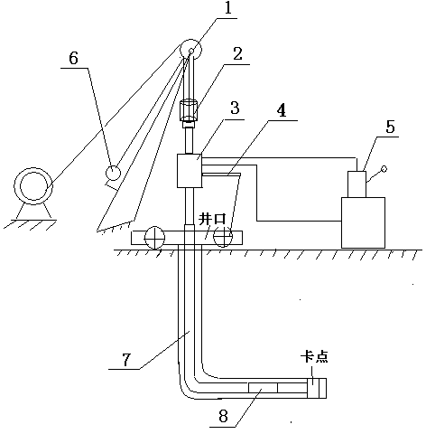
[0032] In order to overcome the deficiencies in the existing method of unblocking in the prior art in the process of unblocking horizontal wells, this embodiment provides a method such as figure 1 The shown horizontal well undercutting method includes the following steps:

[0033] 1) Connect the power swivel 3 to the swimming system 2 of the derrick crane 1, the dead rope end of the derrick crown 1 is connected to the electronic tension gauge 6, the power swivel 3 is connected to the short joint of the tubing, the power swivel 3 and the driving device 5 connections;

[0034] 2) Utilize the swimming system 2 on the derrick crown block 1 to control the lifting or lowering of the power swivel 3, so that the short joint of the tubing on the power swivel 3 is connected with the stuck tubing string 10 in the well;

[0035] 3) Fix the anti-torque balance rope 4 of the power faucet 3, lift the power faucet through the swimming system 2, and make its pulling force equal to the suspend...

Embodiment 2

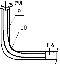
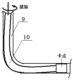
[0047] On the basis of embodiment 1, the principle of the present invention's horizontal well undercutting and jamming release is as follows:

[0048] (1) The lifting force should not be too large, otherwise the amount of stuck tubing string 10 poured out would be too small;

[0049] like figure 2 As shown, when the lifting force is greater than the suspended weight of the stuck pipe string 10 in the well, the stuck pipe string 10 will cling to the inner arc surface of the casing 9 at the transition between the vertical well section and the horizontal section, causing the stuck pipe The resistance of the string 10 is too high during the rotation process, and the torque at the wellhead cannot be transmitted to the position of the stuck point. As a result, the stuck pipe string 10 cannot be reversed from the build-up position during the back-off process, and the stuck pipe string 10 cannot be removed at one time. The pipe string 10 is reversed from the vicinity of the stuck po...


PUM


Abstract

The invention particularly provides a horizontal well reversing clamping release method. A tubular column starts to be reversed, the lifting pull force of a well mouth is controlled through an electronic tension meter, the lifting pull force of the well mouth is approximately equal to the hanging load of the tubular column clamped in a well, the horizontal running torque of the ground is transmitted to a clamping point of the horizontal segment to the maximum extent and changed into the running torque of a vertical plane, and reversing clamping release in the horizontal well segment is achieved. When a part of the clamed tubular column is tripped out of the well, then the rest of the clamped tubular column is reversed through a left-hand screw pipe and a fishing tool, and all parts of the clamped tubular column are tripped out. A driving device is used for driving, the super torque reversing phenomenon is avoided, safety and reliability are achieved, meanwhile, a reversing tool is simple, and the clamping and drilling accident cannot be made to be complicated.

Description

technical field [0001] The invention belongs to the technical field of jam-releasing operations of drilling tools for drilling construction, and in particular relates to a method for unplugging horizontal well undercuts. Background technique [0002] Horizontal wells are a new development model for large-scale development of oil and gas fields. In the process of staged fracturing, pipe sticking often occurs, and most of them can be released in time; only a few key wells cannot be released normally. The investment cost of a horizontal well from drilling to oil production is more than 20 million yuan. If the jam cannot be solved in time, the well cannot be put into oil production in time, which brings huge economic risks to the construction service unit. [0003] At present, the reasons for pipe sticking in horizontal well fracturing construction are as follows: (1) The packer carried by the construction drilling tool does not shrink after construction, and pipe sticking is fo...

Claims


Application Information

Patent Timeline
Patent Type & Authority Applications(China)
IPC IPC(8): E21B31/00E21B21/00
Inventor 邓继学王祖文李尊团魏建荣陈万林任斌高红平景志明米虎宁李继荣左挺韩静静
Owner CHINA NAT PETROLEUM CORP CHUANQING DRILLING ENG CO LTD CHANGQING DOWNHOLE TECH CO
Why Eureka
Try Eureka