A gas turbine spiral tube regenerator

A technology of gas turbines and spiral tubes, which is applied in the direction of gas turbine devices, machines/engines, mechanical equipment, etc., can solve the problems of high welding technology, complex structure, and large pressure loss of processing technology units, and achieve light weight, small volume, The effect of low resistance

Active Publication Date: 2016-03-16
长三角新能源汽车研究院有限公司 +1
View PDF4 Cites 0 Cited by
  • Summary
  • Abstract
  • Description
  • Claims
  • Application Information

AI Technical Summary

Problems solved by technology

[0002] The existing rocker-type regenerators and original surface-type regenerators have complex structures, require high processing technology and unit welding technology, small flow channels, and large pressure loss

Method used


Image

  • A gas turbine spiral tube regenerator
  • A gas turbine spiral tube regenerator
  • A gas turbine spiral tube regenerator

Examples


Embodiment Construction

[0024] In order to make the above objects, features and advantages of the present invention more comprehensible, the present invention will be further described in detail below in conjunction with the accompanying drawings and specific embodiments.

[0025] Reference herein to "one embodiment" or "an embodiment" refers to a particular feature, structure or characteristic that can be included in at least one implementation of the present invention. "In one embodiment" appearing in different places in this specification does not all refer to the same embodiment, nor is it a separate or selective embodiment that is mutually exclusive with other embodiments.

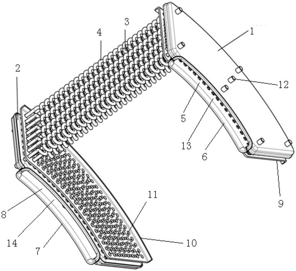
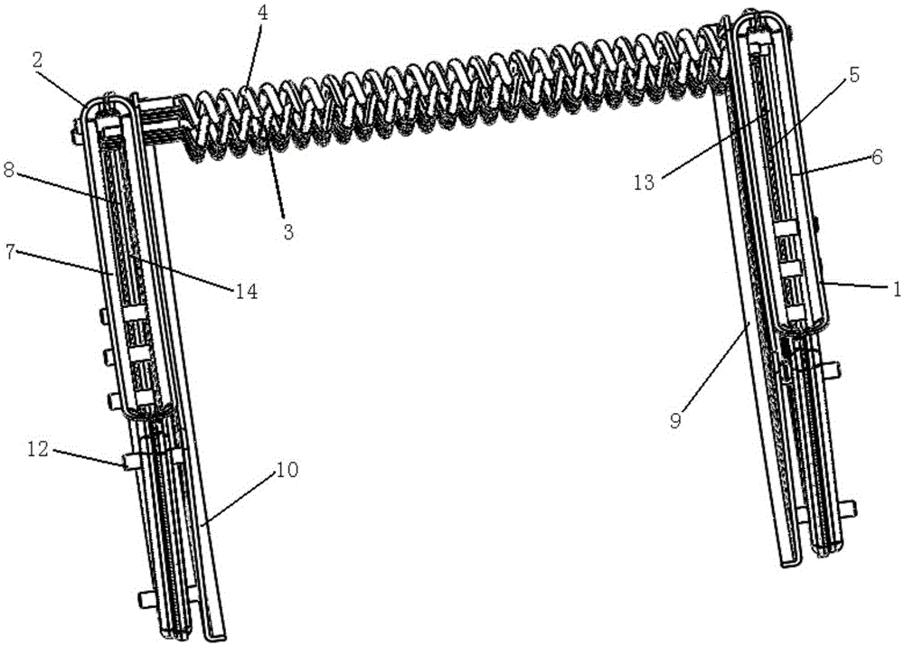
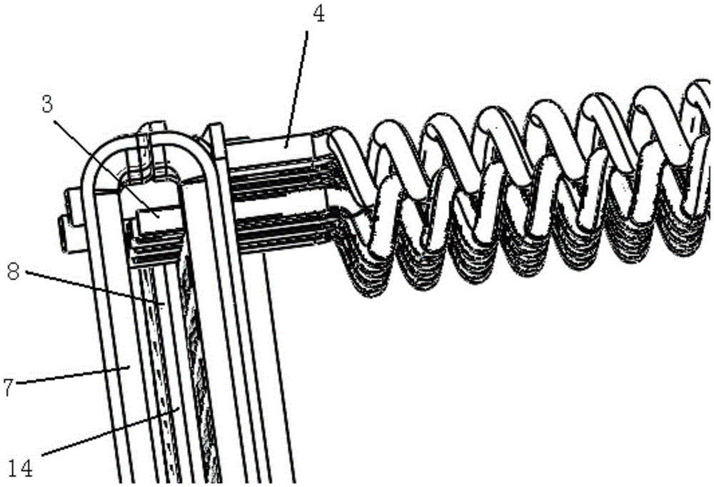
[0026] see Figure 1 to Figure 3 , figure 1 It is a structural schematic diagram of a gas turbine spiral tube type regenerator of the present invention; figure 2 It is a structural schematic diagram of a gas turbine spiral tube type regenerator of the present invention; image 3 yes figure 2 A partially enlarged schema...


PUM


Abstract

The invention provides a spiral pipe type heat regenerator for a gas turbine. The spiral pipe type heat regenerator comprises a first end plate, a second end plate, a plurality of first spiral pipes and a plurality of second spiral pipes, wherein the first end plate is provided with a first air inlet chamber and a first air outlet chamber; the second end plate is provided with a second air inlet chamber and a second air outlet chamber; the first spiral pipes are positioned between the first end plate and the second end plate and are communicated with the first air inlet chamber and the second air outlet chamber; the second spiral pipes are positioned between the first end plate and the second end plate and are communicated with the second air inlet chamber and the first air outlet chamber. Compared with the prior art, the spiral pipe type heat regenerator for the gas turbine has an efficient heat transfer surface, and is light, small in size, convenient to maintain, high in heat regeneration degree, small in resistance and low in cost; the heat transfer area of unit volume is large.

Description

technical field [0001] The invention relates to the field of micro gas turbines, in particular to a micro gas turbine spiral tube regenerator. Background technique [0002] The existing seesaw-type regenerators and original surface-type regenerators have complex structures, require high processing technology and unit assembly welding technology, have small flow channels, and have large pressure losses. [0003] Therefore, it is necessary to make further improvements to the prior art. Contents of the invention [0004] The purpose of the present invention is to overcome the defects of the above-mentioned prior art and provide a gas turbine spiral tube regenerator, which has a high-efficiency heat transfer surface, light weight, small volume, convenient maintenance, high heat recovery, small resistance, and low cost. [0005] In order to achieve the aforementioned purpose, the present invention provides a spiral tube regenerator for a gas turbine, comprising: [0006] a fi...

Claims


Application Information

Patent Timeline
Patent Type & Authority Patents(China)
IPC IPC(8): F02C7/08
Inventor 姬芬竹郭峥嵘史践丁元章周红峰
Owner 长三角新能源汽车研究院有限公司
Why Eureka
Try Eureka