Plate-fin heat regenerator of micro gas turbine

A micro gas turbine, plate-fin technology, applied in the direction of gas turbine devices, indirect heat exchangers, heat exchanger types, etc., can solve the problems of high welding technology, complex structure, small flow path and other problems in the processing technology unit, and achieve weight Light, small size, low resistance effect

Inactive Publication Date: 2020-04-24
长三角新能源汽车研究院有限公司
View PDF0 Cites 4 Cited by
  • Summary
  • Abstract
  • Description
  • Claims
  • Application Information

AI Technical Summary

Problems solved by technology

However, the existing original surface regenerator has a complex structure, requires high processing technology and unit welding technology, small flow channel, and large pressure loss

Method used


Image

  • Plate-fin heat regenerator of micro gas turbine
  • Plate-fin heat regenerator of micro gas turbine

Examples


Embodiment Construction

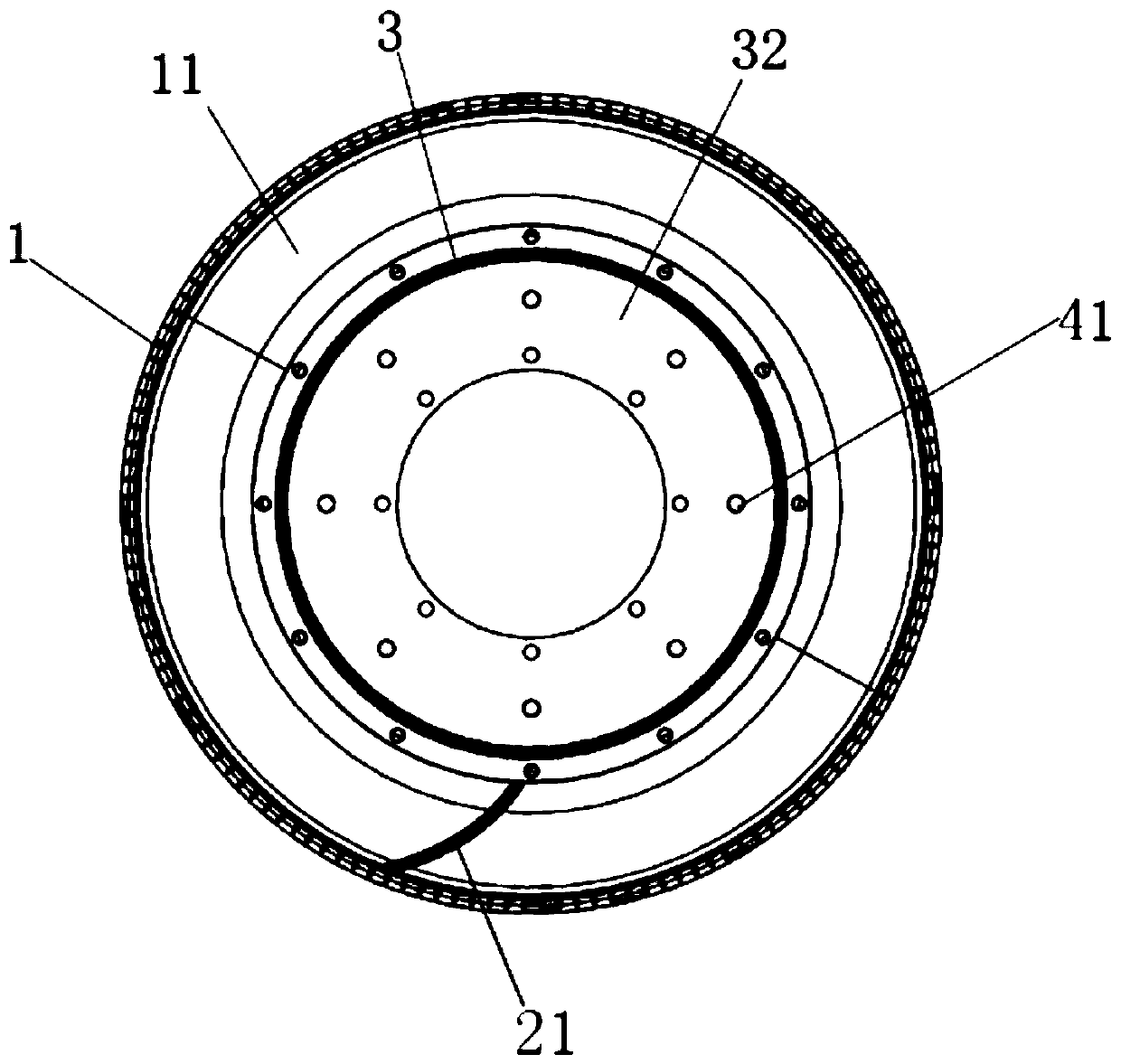
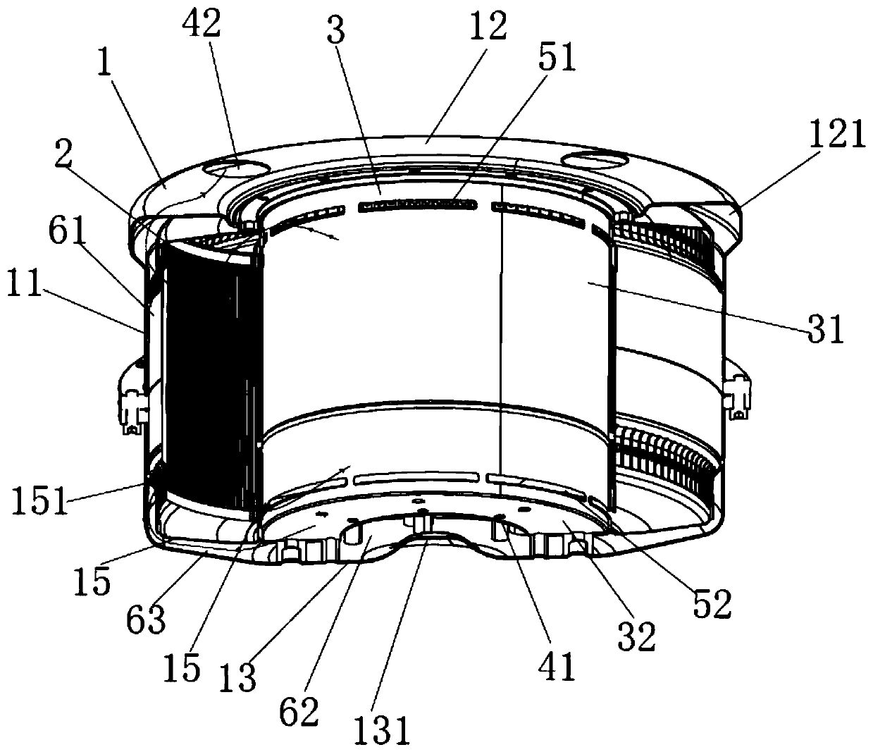
[0026] figure 1 and figure 2 A micro gas turbine regenerator according to an embodiment of the present invention is schematically shown. Such as figure 1 and figure 2 As shown, the micro gas turbine regenerator includes an outer casing 1 , a fin assembly 2 and a thermal insulation casing 3 .

[0027] The outer casing 1 is provided with a casing cavity 61 . The outer casing 1 is covered on the outside of the heat-insulating casing 3 . The fin assembly 2 is disposed in the casing cavity 61 . The fin assembly 2 includes a plurality of fins 21 . The fin 21 is a hollow structure provided with a fin cavity. The fins 21 are arc-shaped, and a plurality of fins 21 form a circular tube around the heat-insulating casing 3, thereby increasing the heat transfer area and improving the heat transfer efficiency.

[0028] The outer casing 1 includes a cylindrical outer casing outer panel 11 and an outer casing inner panel 14 . The two ends of the outer side plate 11 of the outer cas...


PUM


Abstract

The invention provides a micro gas turbine plate-fin heat regenerator which comprises an outer casing, a fin assembly and a heat insulation casing. A shell cavity is formed in the outer casing, and the heat insulation casing is coated with the outer casing. The fin assembly is arranged in the shell cavity and comprises a plurality of fins. Each fin is of a hollow structure provided with a fin cavity. A first air inlet communicated with the shell cavity is formed in the inner bottom of the shell. A first air outlet communicated with the shell cavity is formed in the top of the shell. A second air inlet communicated with a fin cavity is formed in the end, close to the top of the shell, of the inner side wall of the shell. A second air outlet communicated with a fin cavity is formed in the other end, close to the bottom of the shell, of the inner side wall of the shell. The plate-fin heat regenerator is provided with an efficient heat transfer surface, larger in heat transfer area per unit volume, light in weight, small in volume, convenient to maintain, high in heat regeneration degree, small in resistance and low in price.

Description

technical field [0001] The invention belongs to the field of micro gas turbines, and more specifically relates to a plate-fin type regenerator of a micro gas turbine. Background technique [0002] After being compressed in the compressor, the air enters the regenerator, where it absorbs the heat of part of the exhaust gas after doing work, and then enters the combustion chamber. The temperature of the gas is relatively high, and it enters the regenerator to heat the air from the compressor; the exhaust gas discharged from the regenerator passes through a waste heat recovery device to further improve the system efficiency. However, the existing original surface regenerator has a complex structure, requires high processing technology and unit welding technology, and has small flow channels and large pressure loss. Contents of the invention [0003] The object of the present invention is to provide a micro gas turbine regenerator with high-efficiency heat transfer surface an...

Claims


Application Information

Patent Timeline
Patent Type & Authority Applications(China)
IPC IPC(8): F28D9/00F23L15/04F02C7/08
CPCF02C7/08F23L15/04F28D9/0012Y02E20/34
Inventor 周红峰丁元章史践
Owner 长三角新能源汽车研究院有限公司
Why Eureka
Try Eureka