Refrigeration apparatus

a technology of refrigerating apparatus and heat exchanger, which is applied in the direction of refrigeration equipment, refrigeration components, lighting and heating equipment, etc., can solve the problems of difficult to achieve high operating efficiency, large temperature difference between refrigerant and heat exchanger, and high heat radiation loss of heat exchanger, so as to improve the heat transfer coefficient in the flow rate of refrigerant through the low-temperature heat transfer channel can be increased, and the effect of less flow resistan

Active Publication Date: 2010-12-02
DAIKIN IND LTD
View PDF28 Cites 23 Cited by
  • Summary
  • Abstract
  • Description
  • Claims
  • Application Information

AI Technical Summary

Benefits of technology

[0020]In this refrigeration apparatus, since the intercooler is disposed in the upper upwind part, the space for disposing the heat source-side heat exchanger in a upwind part where heat exchange with air would be effective is limited to the lower upwind part below the intercooler, but the lower upwind part is the location of the low-temperature heat transfer channels through which low-temperature refrigerant flows with less flow resistance than the high-temperature refrigerant, and the refrigerant fed from the high-temperature heat transfer channels is mixed in and made to flow into the low-temperature heat transfer channels. Therefore, the flow rate of refrigerant through the low-temperature heat transfer channels can be increased, the heat transfer coefficient in the low-temperature heat transfer channels can be improved, and the heat transfer performance of the heat source-side heat exchanger can be further improved.

Problems solved by technology

As a result, since the refrigerant discharged from the first-stage compression element of the compressor has a high temperature, there is a large difference in temperature between the refrigerant and the air as a heat source in the outdoor heat exchanger functioning as a refrigerant cooler, and the outdoor heat exchanger has much heat radiation loss, which poses a problem in making it difficult to achieve a high operating efficiency.
Therefore, the heat transfer performance of the intercooler is reduced as a result.

Method used


Image

  • Refrigeration apparatus
  • Refrigeration apparatus
  • Refrigeration apparatus

Examples


modification 1

(3) Modification 1

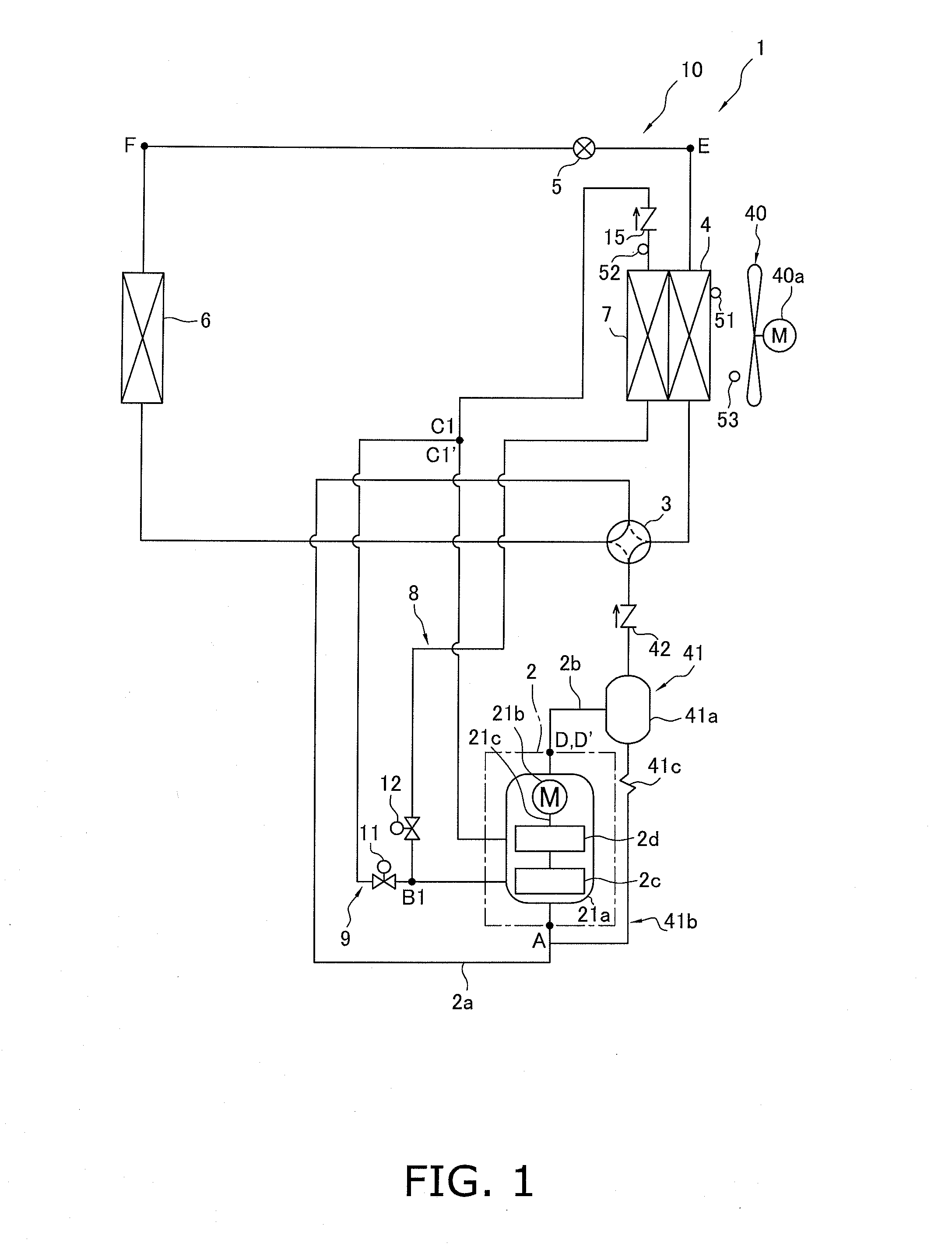
[0111]In the above-described embodiment, a two-stage compression-type compression mechanism 2 is configured from the single compressor 21 having a single-shaft two-stage compression structure, wherein two compression elements 2c, 2d are provided and refrigerant discharged from the first-stage compression element is sequentially compressed in the second-stage compression element, but another possible option is to configure a compression mechanism 2 having a two-stage compression structure by connecting two compressors in series, each of which compressors having a single-stage compression structure in which one compression element is rotatably driven by one compressor drive motor, as shown in FIG. 13.

[0112]The compression mechanism 2 has a compressor 22 and a compressor 23. The compressor 22 has a hermetic structure in which a casing 22a houses a compressor drive motor 22b, a drive shaft 22c, and a compression element 2c. The compressor drive motor 22b is coupled wit...

modification 2

(4) Modification 2

[0114]In the above-described embodiment and the modification thereof, a two-stage-compression-type compression mechanism 2 was used in which two compression elements 2c, 2d were provided and a refrigerant discharged from the first-stage compression element was sequentially compressed by the second-stage compression element as shown in FIGS. 1, 10, and others, but another possible option is to use a three-stage-compression-type compression mechanism 102 in which three compression elements 102c, 102d, 102e are provided, and a refrigerant discharged from the first-stage compression element is sequentially compressed by the second-stage compression element, as shown in FIGS. 14 through 16.

[0115]First, the configuration of the air-conditioning apparatus 1 which performs a three-stage-compression-type refrigeration cycle shown in FIG. 14 will be described. As in the above-described embodiment and the modification thereof, the air-conditioning apparatus 1 herein has a ref...

modification 3

(5) Modification 3

[0145]In the above-described embodiment and the modifications thereof, the configuration has a single compression mechanism 102 and the multistage-compression-type compression mechanism 2 in which refrigerant is sequentially compressed by a plurality of compression elements as shown in FIGS. 1 and 13 through 16, but another possible option, in cases in which, for example, a large-capacity usage-side heat exchanger 6 is connected or a plurality of usage-side heat exchangers 6 is connected, is to use a parallel multistage-compression-type compression mechanism in which a multistage-compression-type compression mechanism 2 and a plurality of compression mechanisms 102 are connected in parallel.

[0146]For example, in the embodiment described above as shown in FIG. 21, the refrigerant circuit 210 can use a compression mechanism 202 configured having a parallel connection between a two-stage-compression-type first compression mechanism 203 having compression elements 203c...


PUM


Abstract

An air-conditioning apparatus uses carbon dioxide as a refrigerant, and includes comprises a two-stage-compression-type compression mechanism, a heat source-side heat exchanger, an expansion mechanism, a usage-side heat exchanger, and an intercooler. The intercooler uses air as a heat source. The intercooler is configured and arranged to cool refrigerant flowing through an intermediate refrigerant tube that draws refrigerant discharged from the first-stage compression element into the second-stage compression element. The intercooler is integrated with the heat source-side heat exchanger to form an integrated heat exchanger, with the intercooler disposed in an upper part of the integrated heat exchanger.

Description

TECHNICAL FIELD[0001]The present invention relates to a refrigeration apparatus, and particularly relates to a refrigeration apparatus which performs a multistage compression refrigeration cycle by using a refrigerant that operates in a supercritical range.BACKGROUND ART[0002]As one conventional example of a refrigeration apparatus which performs a multistage compression refrigeration cycle by using a refrigerant that operates in a supercritical range, Patent Document 1 discloses an air-conditioning apparatus performs a two-stage-compression refrigeration cycle by using carbon dioxide as a refrigerant. This air-conditioning apparatus has primarily a compressor having two compression elements connected in series, an outdoor heat exchanger as a heat source-side heat exchanger, an expansion valve, and an indoor heat exchanger.[0003]<Patent Document 1>[0004]Japanese Laid-open Patent Application No. 2007-232263DISCLOSURE OF THE INVENTION[0005]A refrigeration apparatus according to ...

Claims


Application Information

Patent Timeline
Patent Type & Authority Applications(United States)
IPC IPC(8): F25B1/00F25B41/00F28F1/10
CPCF25B1/10F25B9/008F25B13/00F25B31/004F25B39/00F25B2600/17F25B2313/02741F25B2400/075F25B2400/13F25B2400/23F25B2309/061F25B2400/072
Inventor FUJIMOTO, SHUJIYOSHIMI, ATSUSHIUENO, YOSHIOFUJIYOSHI, RYUSUKEKURIHARA, TOSHIYUKIYOSHIOKA, SHUN
Owner DAIKIN IND LTD
Why Eureka
Try Eureka