In-place surface topography detection workbench

A technology for detecting workbench and surface topography, which is applied in the direction of measuring devices, instruments, and optical devices, etc., can solve the problems that the displacement workbench cannot achieve real-time on-site measurement, the overall volume of the workbench is large, and the detection is troublesome, etc., to achieve The effect of wide application range, shortened height space, and small volume

Active Publication Date: 2014-12-10
HUAQIAO UNIVERSITY
View PDF6 Cites 9 Cited by
  • Summary
  • Abstract
  • Description
  • Claims
  • Application Information

AI Technical Summary

Problems solved by technology

Most of the traditional displacement tables adopt a two-layer superimposed structure, that is, the parts that move in the X-axis axial direction and the parts that move in the Y-axis axial direction are distributed on the upper and lower layers. It is large and has a complex structure, so that the displacement table cannot perform real-time on-site measurement due to space constraints during the on-site measurement. The measured object can only be disassembled and placed on the displacement table for detection. come to trouble

Method used


Image

  • In-place surface topography detection workbench
  • In-place surface topography detection workbench
  • In-place surface topography detection workbench

Examples


Embodiment Construction

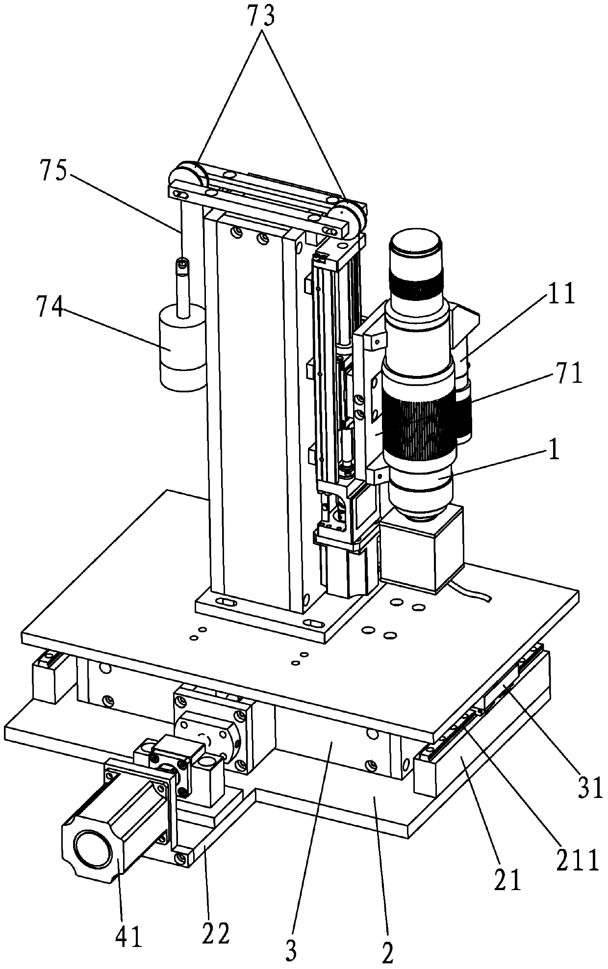
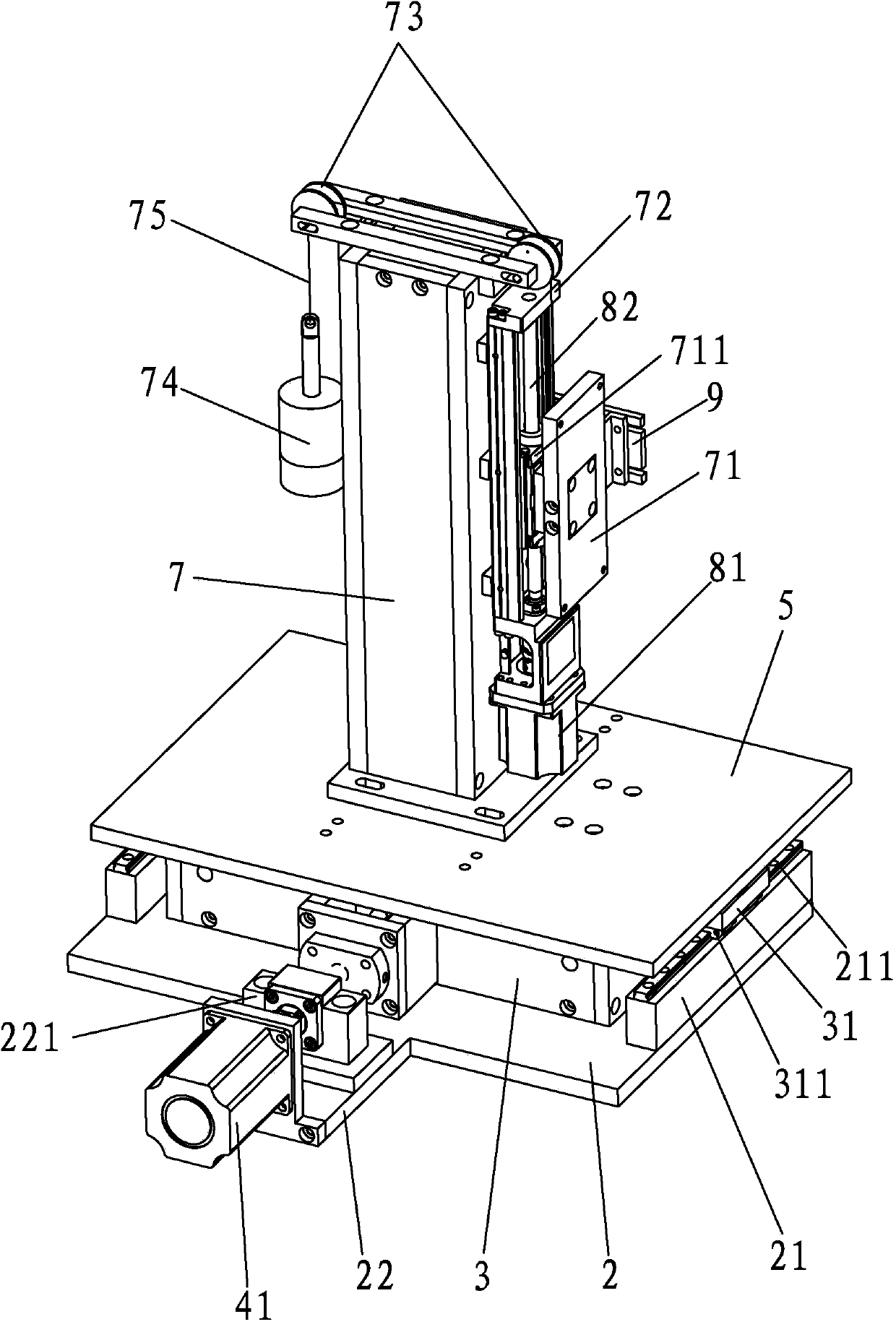
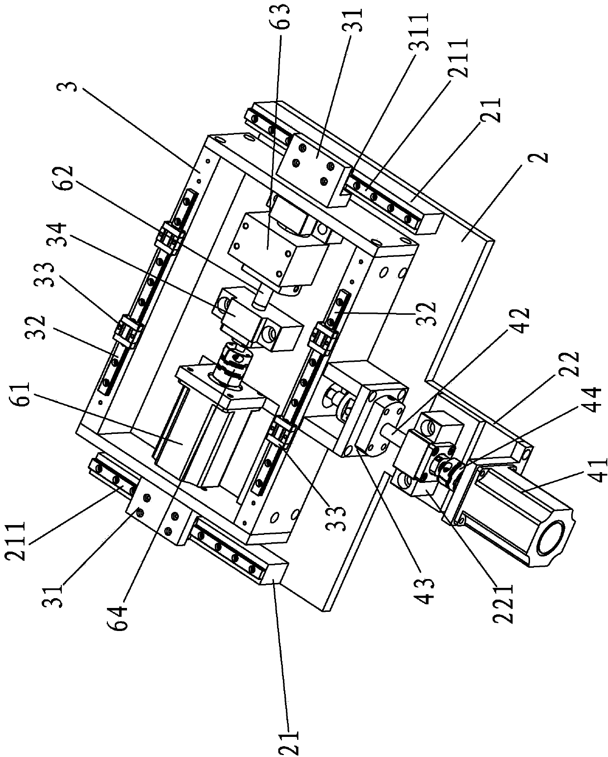
[0036] An in-situ surface topography detection workbench of the present invention, such as Figure 1-3 Shown, comprise support and microscope 1, support comprises lower base plate 2 and upper frame body 3, and this lower base plate 2 is a square plate, and this upper frame body 3 is the hollow square frame body that its upper end is open shape, upper frame body 3. It can be erected above the upper surface of the lower base plate 2 in a manner of translating and sliding along the front-rear direction of the lower base plate 2, that is, the left and right sides of the upper surface of the lower base plate 2 are protrudingly provided with X-axis guide rails 21 extending along the front-rear direction of the lower base plate 2, The upper surface of the X-axis guide rail 21 is protrudingly provided with an X-axis slide rail 211 extending along the length direction of the X-axis guide rail 21, and the left and right outer walls of the upper frame body 3 are provided with one arm fixe...


PUM


Abstract

The invention discloses an in-place surface topography detection workbench which comprises a base and a microscope. The base comprises a lower base plate and an upper frame body, wherein the upper frame body is a hollow frame body with an opening-shaped upper end and is erected above the upper surface of the lower base plate in a mode that the upper frame body can translate and slide in the front-back direction of the lower base plate, an X-axis translation driving device controlling front-back sliding of the upper frame body is arranged on the front side or the rear side of the lower base plate, a placement platform capable of translating along the upper frame body in a left-right mode is erected on the upper end face of the upper frame body, a Y-axis translation driving device controlling left-right movement of the placement platform is arranged in the upper frame body, an installing column is vertically arranged on the placement platform, an installing block capable of vertically moving is arranged on the installing column, the microscope is installed on the installing block, and a Z-axis lifting driving device for controlling vertical movement of the installing block is installed on the installing column. The in-place surface topography detection workbench has the advantages of being capable of achieving in-place offline measurement, wide in application range and simple, reasonable and compact in whole structure.

Description

technical field [0001] The invention relates to a detection workbench, in particular to an in-situ surface topography detection workbench. Background technique [0002] Precise shape detection is a very important part of modern technology. The quality of the product is controlled by detecting the structural size or the accuracy of the surface shape of the object to be tested. There are various detection methods for shape detection. Among them, the measurement technology of optical non-contact detection method can obtain accurate shape data of the surface of the object to be measured in a non-destructive way. It has been widely used in various industries, especially On-site detection of the object to be tested. [0003] The most important part of the existing in-situ shape detection system is the displacement workbench, which is a generalized operation platform with an operation surface for direct or indirect clamping or placing the object to be measured, which can be adjust...

Claims


Application Information

Patent Timeline
Patent Type & Authority Applications(China)
IPC IPC(8): G01B11/24
Inventor 崔长彩陈俊英陈伟鹏李兵余卿
Owner HUAQIAO UNIVERSITY
Why Eureka
Try Eureka