Blood component separation device

A blood component and separation device technology, applied in the direction of blood transfusion devices, drug devices, suction devices, etc., can solve the problems of unable to control the amount of platelet fluid collection, constant amount, platelet fluid changes, etc.

Active Publication Date: 2014-12-10
TERUMO KK
View PDF5 Cites 2 Cited by
  • Summary
  • Abstract
  • Description
  • Claims
  • Application Information

AI Technical Summary

Problems solved by technology

Therefore, there is a problem that the amount of platelet fluid collected in each cycle cannot be controlled to a constant amount, resulting in a change in the amount of platelet fluid finally collected after a plurality of cycles.

Method used


Image

  • Blood component separation device
  • Blood component separation device
  • Blood component separation device

Examples


Embodiment 1

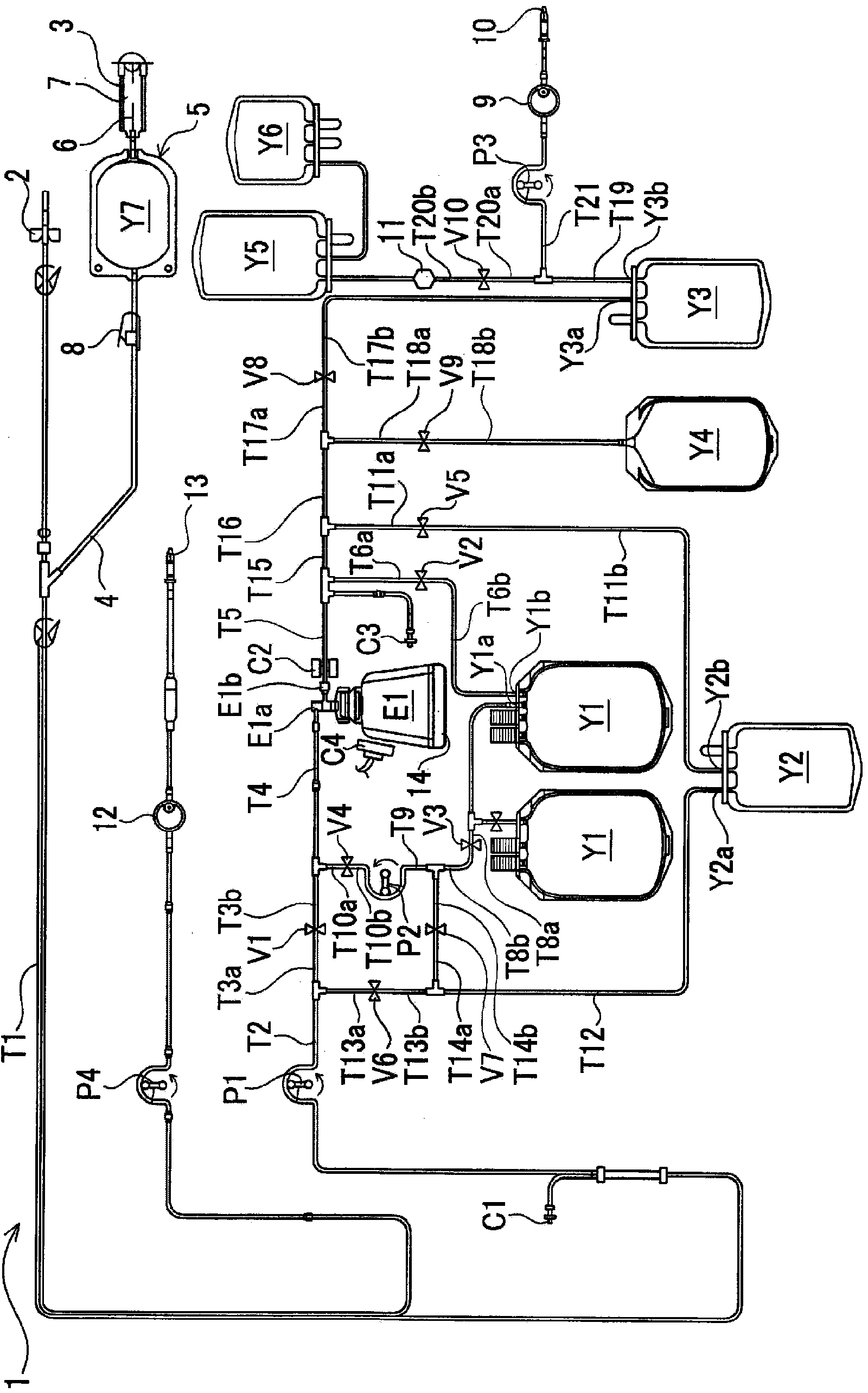
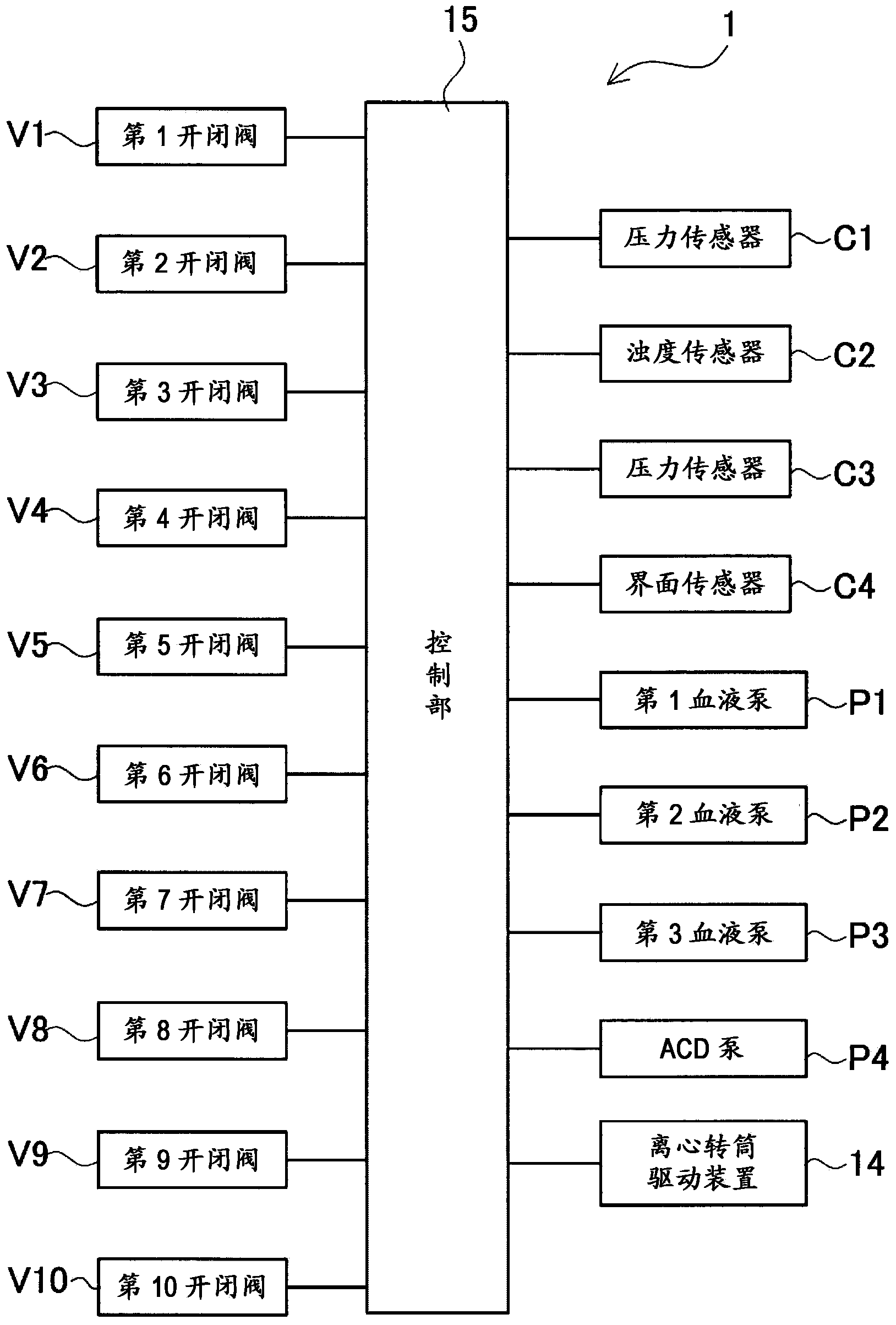
[0071] The system configuration of the blood component separation device of Example 1 is shown in figure 1 . figure 2 It is a block diagram showing a control system of the blood component separation device according to the embodiment.

[0072] The blood component separation device according to this embodiment includes a blood component separation circuit 1 . The blood component separation circuit 1 has an initial blood collection circuit 5, and the initial blood collection circuit 5 includes: a blood collection needle 2, an initial blood collection bag Y7 for collecting initial blood, a sampling port (sampling port) 3, and an initial blood collection circuit 4 .

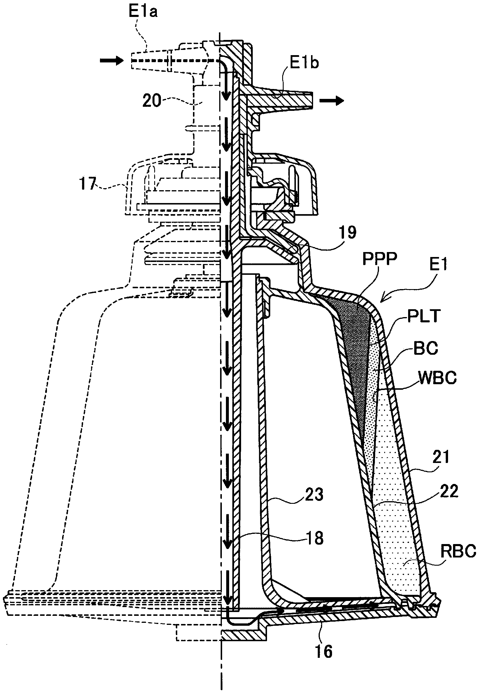
[0073] In addition, the blood component separation circuit 1 has a centrifuge bowl E1. The centrifuge bowl E1 has a rotor (not shown) having a blood storage space inside the collection, a rotary drive mechanism 14 for rotationally driving the rotor, an inflow port (first port E1a) and an outflow port (second port...

Embodiment 2

[0157] Next, Example 2 will be described, but the same symbols will be attached to the same components as those in Example 1, and description will be omitted, and the description will focus on differences. The blood component separation device of Example 2 differs from the blood component separation device of Example 1 mainly in that BC recovery (recycle) is not used. Here, the system configuration of the blood component separation device of Example 2 is shown in Figure 27 . The main difference between the blood component separation circuit 30 of the second embodiment and the first embodiment is that it does not have the temporary storage bag Y2.

[0158] Therefore, the operation of the blood component separator of the second embodiment will be described. here, Figure 28 is a flowchart showing the operation of the blood component separation device, Figure 29 ~ Figure 31 The function and process of the blood component separation device are shown.

[0159] For the blood ...


PUM


Abstract

This blood component separation device: is provided with a centrifugal separator for separating a plurality of prescribed blood components from blood, and a container for holding the prescribed blood components that have been centrifugally separated; and performs a step in which the separated plurality of blood components are each collected over a plurality of cycles. The blood component separation device performs a step in which the starting point of the step for collecting the prescribed blood components is determined from blood count values of a donor on the basis of map data pertaining to pre-stored blood count values or the concentrations of prescribed blood components, in such a manner that the concentrations of the prescribed blood components become equal at each point that the blood components are discharged from the centrifugal separator at the collection starting point and finishing point in the step for collecting the prescribed blood components.

Description

technical field [0001] The present invention relates to a blood component separation device for collecting a predetermined blood component from blood. More specifically, it relates to a blood component separation device that collects a predetermined amount of blood components in each cycle. Background technique [0002] Conventionally, component blood collection in which only platelets and the like are collected and other components are returned to the blood donor has been mainly performed in blood collection. In this case, a blood component separator having a centrifugal separator is used. [0003] In recent years, blood transfusion of platelet fluid has been widely performed in radiotherapy for cancer, etc., and in this case, high-concentration platelet fluid is required. In order to collect high-concentration platelet fluid, the technique of Patent Document 1 is carried out as follows: In the blood component separation device, low-concentration platelet fluid is temporar...

Claims


Application Information

Patent Timeline
IPC IPC(8): A61M1/02
CPCA61M1/3696A61M1/3693A61M1/0209A61M2202/0427
Inventor 木村重幸
Owner TERUMO KK
Why Eureka
Try Eureka