Aircraft turbojet engine exhaust cone

A gas jet, cone technology, applied in the direction of machines/engines, aircraft parts, jet propulsion devices, etc., can solve problems such as long time

Inactive Publication Date: 2014-12-10
AIRCELLE
View PDF6 Cites 3 Cited by
  • Summary
  • Abstract
  • Description
  • Claims
  • Application Information

AI Technical Summary

Problems solved by technology

[0014] The removal operation takes a long time to perform and requires the intervention of multiple operators, especially if relatively heavy parts are being handled

Method used


Image

  • Aircraft turbojet engine exhaust cone
  • Aircraft turbojet engine exhaust cone
  • Aircraft turbojet engine exhaust cone

Examples


Embodiment Construction

[0043] In the ensuing description the terms "front" and "rear" will be used.

[0044] The above terms are to be understood relative to the direction of air circulation in the nacelle when the turbojet engine is in operation.

[0045] More specifically, the front and rear are located on the left and right sides of each drawing, respectively.

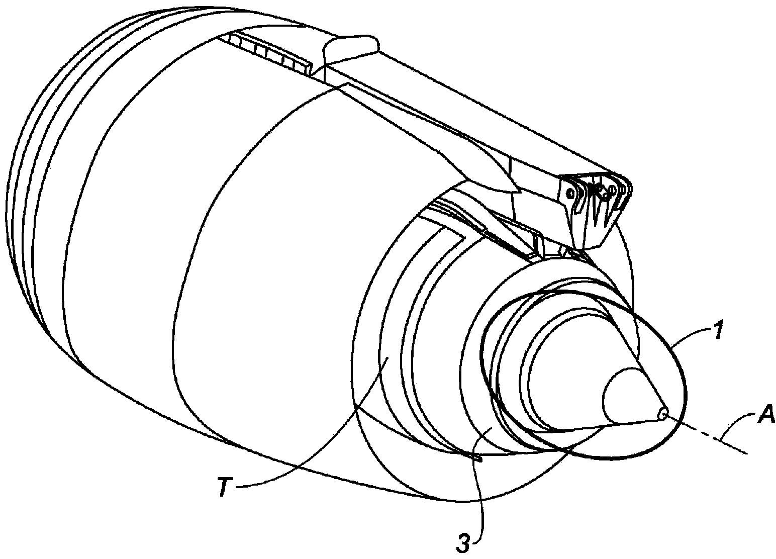
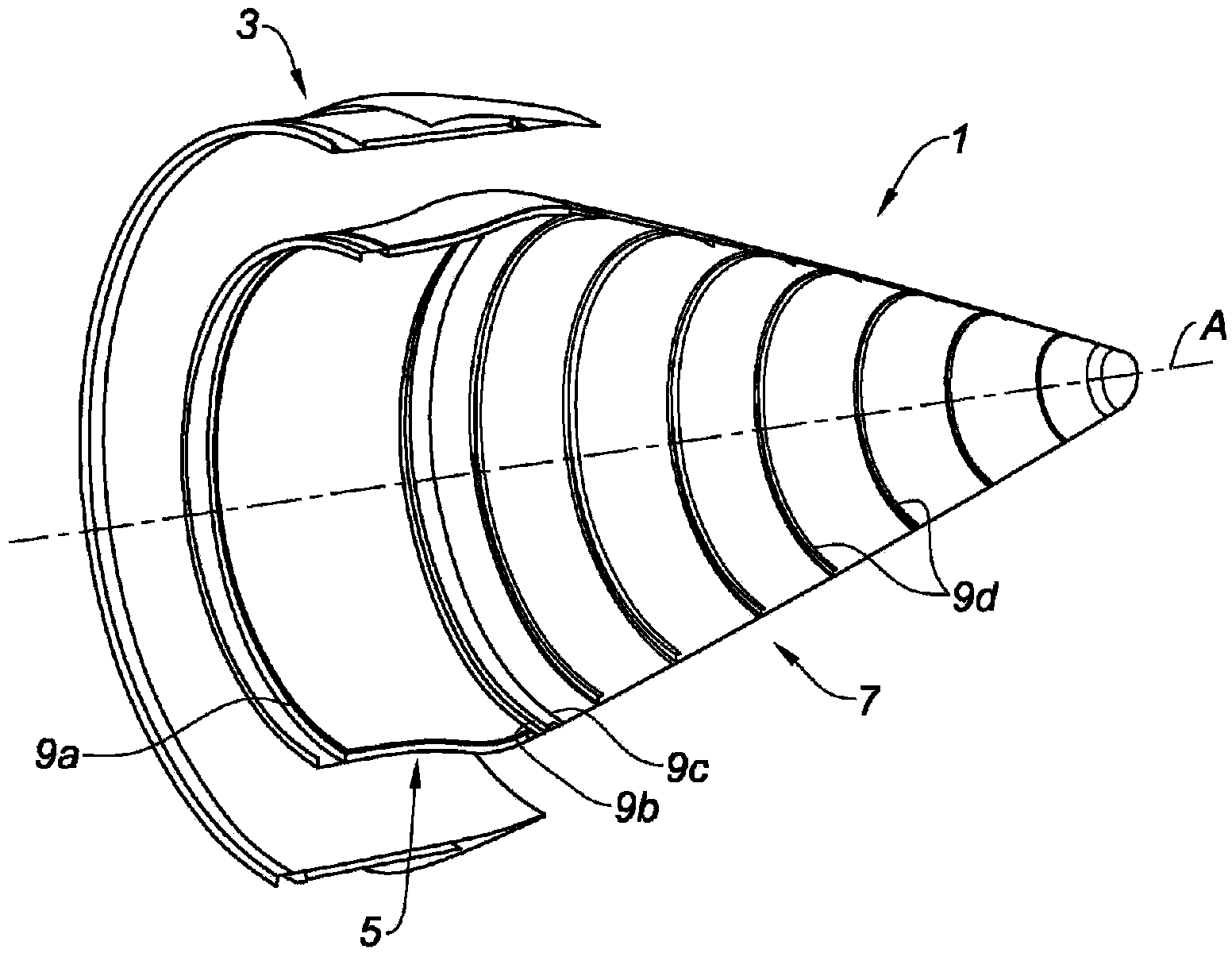
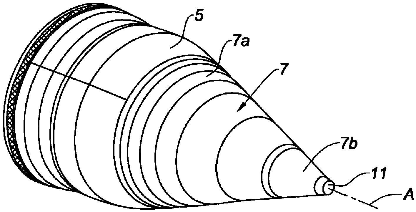
[0046] image 3 and Figure 4 The spray cone 1 according to the invention is shown comprising two main parts, namely a substantially cylindrical front cone part 5 and a substantially conical rear cone part 7 .

[0047] As mentioned earlier in the description, the front cone portion 5 and the rear cone portion 7 may be non-detachably connected to each other, such as by welding, or may be detachably connected to each other, such as by screws, as image 3 and Figure 4 Example shown.

[0048] The rear cone portion 7 sequentially includes a front sub-section 7a and a rear sub-section 7b detachably connected thereto, for example, by screw...


PUM


Abstract

The invention relates to an exhaust cone (1) comprising: a substantially cylindrical front cone part (5); a substantially conical rear cone part (7); a drainage and/or ventilation tube (11) extending inside the front (5) and rear (7) cone parts and emerging at the end of the rear cone part; and a support bearing (13) for supporting the drainage and/or ventilation tube, arranged inside the rear cone part (7). The exhaust cone (1) is characterised in that the rear cone part (7) in turn comprises a front sub-part (7a) connected to the front cone part (5) and a rear sub-part (7b) removably secured to the front sub-part (7a) and equipped with an outlet for the drainage and/or ventilation tube (11).

Description

technical field [0001] This patent application relates to gas injection cones for aircraft turbojet engines. Background technique [0002] known, such as figure 1 As shown, in order to optimize on the one hand the flow of hot air discharged by the turbojet engine, and on the other hand to absorb at least part of the noise generated by the interaction of said hot air with the surrounding air and with the flow of cold air discharged by the fan of the turbojet engine, usually At the rear of the turbojet engine T of the aircraft is provided an injection cone 1 . [0003] as attached figure 2 A conventional injection cone 1 is shown, upstream and downstream (with respect to the flow direction of the injection air of the turbojet engine) on the left and right sides of the drawing, respectively. [0004] Said cone is located downstream of the turbojet T, coaxially with the casing or nozzle 3 and is in turn fixed at the downstream edge of the turbojet T's combustion chamber. ...

Claims


Application Information

Patent Timeline
Patent Type & Authority Applications(China)
IPC IPC(8): F02K1/04
CPCF02K1/04B64C7/02F02K1/36
Inventor 帕斯卡-玛丽·保罗·马塞尔·苏利耶让-伯纳德·居伊隆让-皮埃尔·盖古
Owner AIRCELLE
Why Eureka
Try Eureka