Hydraulic damper with adjustable rebound valve assembly

A hydraulic damper, damper technology, applied in the direction of spring/shock absorber, spring, shock absorber, etc., can solve the problems of deviation, inflection point position uncertainty, low repeatability of opening torque, etc.

Active Publication Date: 2016-04-20
BEIJING WEST IND CO LTD
View PDF9 Cites 0 Cited by
  • Summary
  • Abstract
  • Description
  • Claims
  • Application Information

AI Technical Summary

Problems solved by technology

However, in this type of deflate rebound valve assembly, where the centrally located generally rigid disc is preloaded by a compression spring, such a Relatively low repeatability of the opening torque of the rebound valve assembly, leading to uncertainty in the position of the knee point and unpredictable deviations of the observed force-velocity characteristics from the theoretical ones
Furthermore, in prior art dampers as described above, only the inclination and position of the inflection point of the second part of the characteristic can be adjusted by proper choice of compression spring stiffness and preload

Method used


Image

  • Hydraulic damper with adjustable rebound valve assembly
  • Hydraulic damper with adjustable rebound valve assembly
  • Hydraulic damper with adjustable rebound valve assembly

Examples


Embodiment Construction

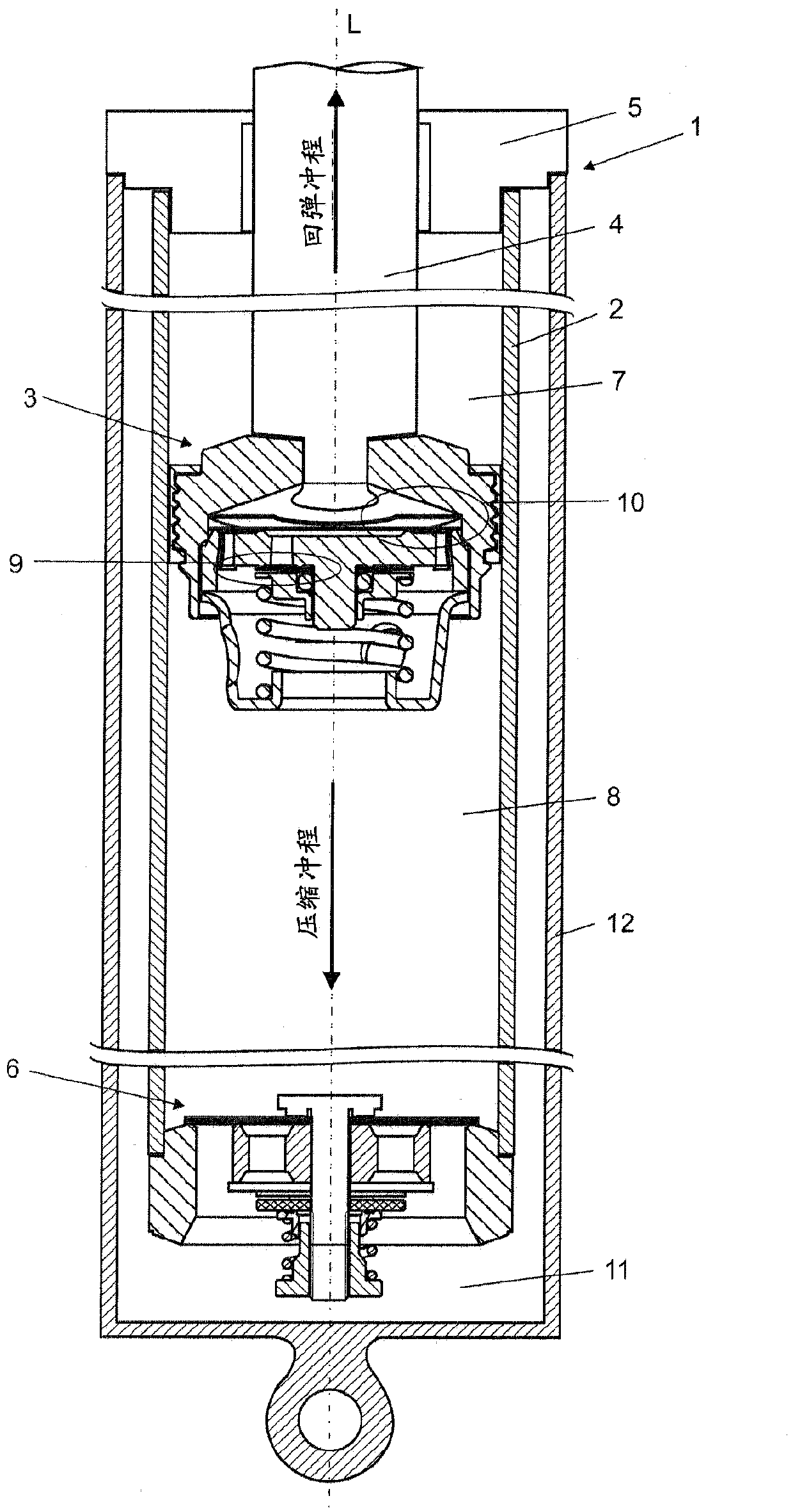
[0019] figure 1 The hydraulic damper 1 shown in is an example of a two-tube damper. Inside the inner tube 2 filled with working fluid, there is a slidable piston assembly 3 . The piston assembly 3 is connected to a piston rod 4 which is guided axially to the outside of the damper 1 via a sealed piston rod guide 5 . At the other end of the tube 2, a base valve assembly 6 is provided. The piston assembly 3 is in sliding fit with the inner surface of the tube 2 and divides the tube 2 into a rebound chamber 7 and a compression chamber 8 . The piston assembly 3 also includes a rebound valve assembly 9 and a compression valve assembly 10 with flow passages to control the flow of working fluid through the piston assembly 3 during the rebound stroke and the compression stroke of the damper 1 . The base valve assembly 6 is also provided with a rebound valve assembly and a compression valve assembly having a flow passage to control the flow of working fluid between the compression ch...


PUM


Abstract

A hydraulic damper (1) includes an orifice plate (33) provided with through rebound flow means and rebound valve means which cover a compression side of the through rebound flow means. A cage member (34) is fixed to a piston assembly at the compression side thereof and is provided with at least one passage (341, 343). A compression spring (95) is preloaded between the cage member (34) and the rebound valve means to normally close the compression side of the through rebound flow means. The orifice plate (33) includes an axial projection (334) and the through rebound flow means include a number of rebound flow passages (332) disposed around the projection (334). The rebound valve means comprise a deflectable disc (91) and an elliptical disc (92) disposed slidably one on top of the other over the axial projection (334).

Description

technical field [0001] The present invention relates to a hydraulic damper, in particular to a motor vehicle suspension damper, comprising at least one tube filled with working fluid, a piston assembly capable of sliding is arranged inside the tube to divide the tube into a compression chamber and a rebound chamber. chamber, the piston assembly is connected to the piston rod which is guided to the outside of the damper through the seal rod guide, and has a rebound valve assembly and a compression valve assembly to control the working fluid during the rebound stroke and compression stroke of the damper Flow through the piston assembly, wherein the piston assembly includes: a body fixed to the piston rod and provided with at least one passage for the free flow of working fluid between the rebound chamber and the inner chamber in the piston body an orifice plate provided with a rebound flow device and a rebound valve device covering the compression side of the rebound flow device...

Claims


Application Information

Patent Timeline
Patent Type & Authority Patents(China)
IPC IPC(8): F16F9/348F16F9/00
CPCF16F9/512F16F9/348F16F9/5126
Inventor P·A·弗拉赤特R·P·戈尔泽斯克
Owner BEIJING WEST IND CO LTD
Why Eureka
Try Eureka