
An arc bending machine used for arc bending and forming of door frame flat iron

A flat iron and arc bending technology is applied in the field of door frame production and processing equipment, which can solve the problems of increased flat iron production and processing costs, affecting the production efficiency of manufacturers, unable to guarantee the production quality of flat iron, etc., so as to improve the flat iron bending and arc forming. Efficiency, improving the efficiency of bending arc forming, the effect of good versatility

Inactive Publication Date: 2017-03-08
广州精准机械有限公司
View PDF8 Cites 0 Cited by
  • Summary
  • Abstract
  • Description
  • Claims
  • Application Information

AI Technical Summary

Problems solved by technology

In the process of using the pipe bender to bend the flat iron, in order to ensure the bending effect of the flat iron, it is usually necessary to reserve some margin on both sides of the flat iron for bending to facilitate the clamping and positioning of the pipe bender. After the arc is completed It is also necessary to cut off the reserved margin, which makes the whole flat iron arc bending operation cumbersome, and increases the production and processing cost of the arc bent flat iron; The production quality of flat iron arc forming, and for the production of a large number of civil air defense doors, the uniformity between them is difficult to be guaranteed, which affects the production efficiency of manufacturers

Method used


Image

  • An arc bending machine used for arc bending and forming of door frame flat iron
  • An arc bending machine used for arc bending and forming of door frame flat iron
  • An arc bending machine used for arc bending and forming of door frame flat iron

Examples


Embodiment Construction

[0016] The present invention will be further described below in conjunction with specific embodiments:

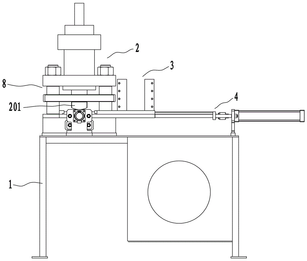
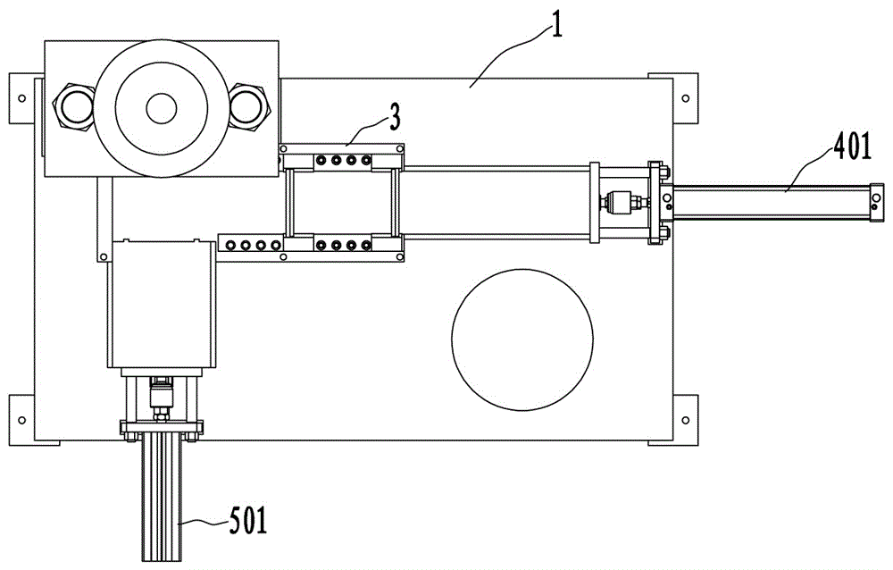
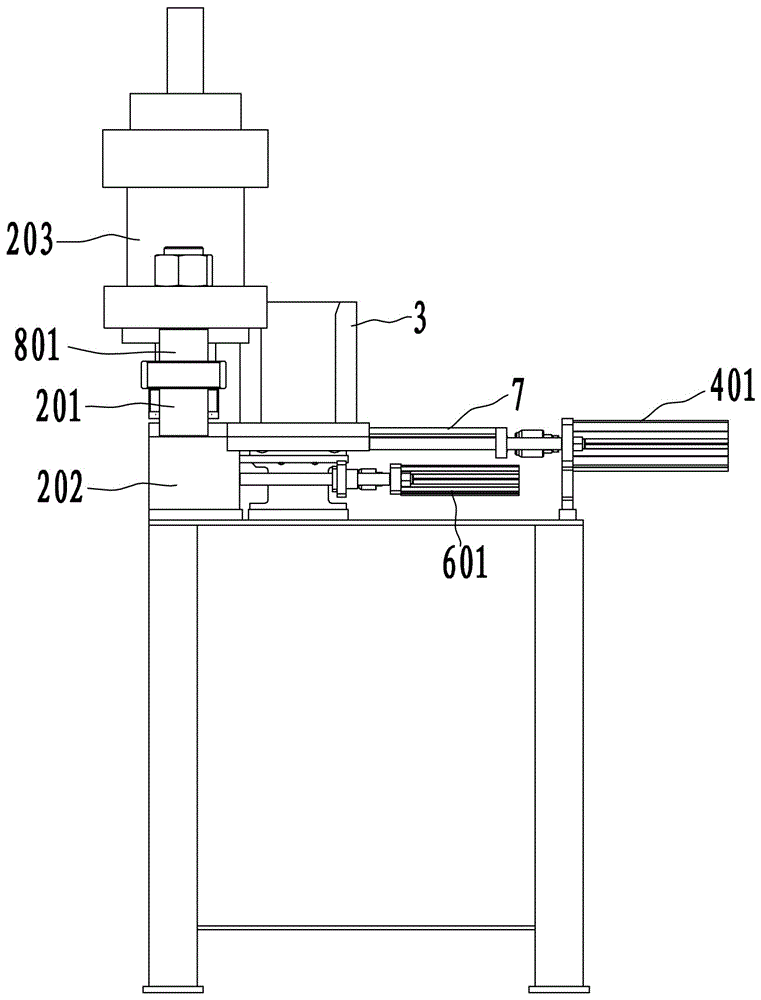
[0017] See attached figure 1 Attached Figure 4 As shown, the arc bending machine used for bending and forming door frame flat iron according to this embodiment includes a frame 1, a pusher assembly 4 arranged in sequence along the longitudinal direction of the frame 1, and The silo 3 for storing flat irons and the flat iron bending assembly 2, wherein the pushing assembly 4 is used to push the flat irons in the silo 3 into the flat iron bending assembly 2 for arc forming. At the same time, a side adjacent to the flat iron bending assembly 2 is also provided with a feeding assembly 5 for feeding the flat iron pushed out of the silo 3 into the flat iron bending assembly 4 by the pushing assembly 4. In addition, this solution also includes a discharging assembly 6 for pushing out the flat iron after the arc forming in the flat iron bending assembly 2.

[0018] In order to furthe...


PUM


Abstract

The invention provides a bending machine for shaping flat irons for doorframes into arcs, which comprises a chassis, a flat iron-bending assembly, a storage bin, a pushing assembly, a feed assembly and a discharge assembly, the flat iron-bending assembly is arranged on the chassis, the storage bin is used for storing flat irons, the pushing assembly is used for pushing the flat irons out of the storage bin, the feed assembly is used for feeding the flat irons pushed out by the pushing assembly into the flat iron-bending assembly, and the discharge assembly is used for pushing the arc-shaped flat irons out of the flat iron-bending assembly; the flat iron-bending assembly comprises an upper bending die press head, a lower bending die press head fixed on the chassis and a bending die-driving oil cylinder for driving the upper bending die press head to move up and down. The bending machine greatly increases the efficiency of shaping the flat irons into arcs, meanwhile, by means of the arc-shaping machining of the flat iron-bending assembly and the pressure shaping method of the upper press die and the lower press die, machining allowances do not need to be set for the flat irons to be bended, so that the production cost of enterprises is reduced effectively, and meanwhile, by means of the press shaping of the upper press die and the lower press die, the uniformity of the arc-shaped flat irons can be ensured to the max.

Description

Technical field [0001] The invention relates to the technical field of door frame manufacturing and processing equipment, and in particular to an arc bending machine used for bending and forming a door frame flat iron. Background technique [0002] During the manufacturing process of the civil air defense door, a section of circular arc flat iron is needed for excessive connection between the frames of the door frame. In the actual production engineering of the existing civil air defense doors, especially for those small workshop-style air defense door processing and production modes, in the manufacturing process of bending the arc flat iron, most of them are used for bending pipes. The pipe bending machine performs flat iron bending arc. In order to ensure the arc bending effect of the flat iron when the pipe bender is used for the flat iron arc operation, it is usually necessary to reserve some margin on both sides of the flat iron for the bending arc to facilitate the clampin...

Claims


Application Information

Patent Timeline
Patent Type & Authority Patents(China)
IPC IPC(8): B21D53/74B21D22/02B21D43/02B21D37/12B21D45/02
Inventor 崔锋
Owner 广州精准机械有限公司
Learn More