
A three-dimensional rapid lead arc forming method and device

A lead, three-dimensional technology, applied in the field of three-dimensional fast lead arc forming methods and devices, can solve the problems of low production efficiency, waste of time, and decrease in chip yield, so as to improve efficiency, simplify complex motion, and avoid lead damage and breakage. Effect

Active Publication Date: 2020-03-13
GUANGDONG UNIV OF TECH
View PDF13 Cites 0 Cited by
  • Summary
  • Abstract
  • Description
  • Claims
  • Application Information

AI Technical Summary

Problems solved by technology

The disadvantage of this idea is that the hacking knife consumes a lot of time and cost in production because of the complex hacking knife trajectory, and the hacking knife movement occupies more than 90% of the lead time, resulting in low production efficiency; and because of the large number of shape parameters. The control of the riving knife is more difficult, and in different applications, a lot of time is wasted in the debugging process for different riving knife trajectories; in addition, the breakpoint of the lead wire is made by forcibly pressing with other contact tools, which can easily cause the breakage of the lead wire. Unnecessary damage and breakage, resulting in a significant drop in chip yield

Method used


Image

  • A three-dimensional rapid lead arc forming method and device
  • A three-dimensional rapid lead arc forming method and device
  • A three-dimensional rapid lead arc forming method and device

Examples


Embodiment 1

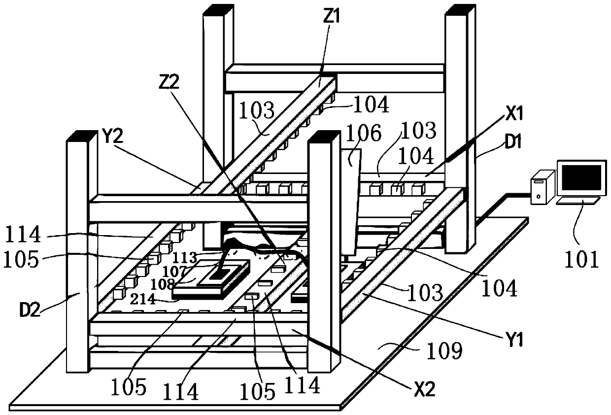
[0035] A three-dimensional rapid lead arc forming method, such as Figure 1-3 shown, including the following steps:

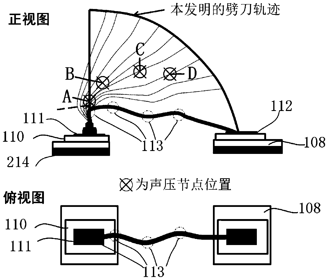
[0036] Step S1: After forming the first solder joint on the first pad 111, the free end of the lead wire 107 is fixed by the rivet 106, and the ultrasonic sounding unit 103 emits ultrasonic waves through the radiating end 104 of the ultrasonic transducer, and at the radiating end 104 of the ultrasonic transducer A sound pressure node is formed in the resonant space between the reflecting unit 105;

[0037] Step S2: During the movement of the hacker 106 according to the pre-designed three-dimensional trajectory of the computer program, use the spatial fine-tuning of the radiation end 104 of the ultrasonic transducer and the corresponding reflection unit 105 in the space to make the sound pressure node in the resonance space at Move freely within a certain range, and use the sound field radiation force at the sound pressure node to bend the lead 107, thereby pre...

Embodiment 2

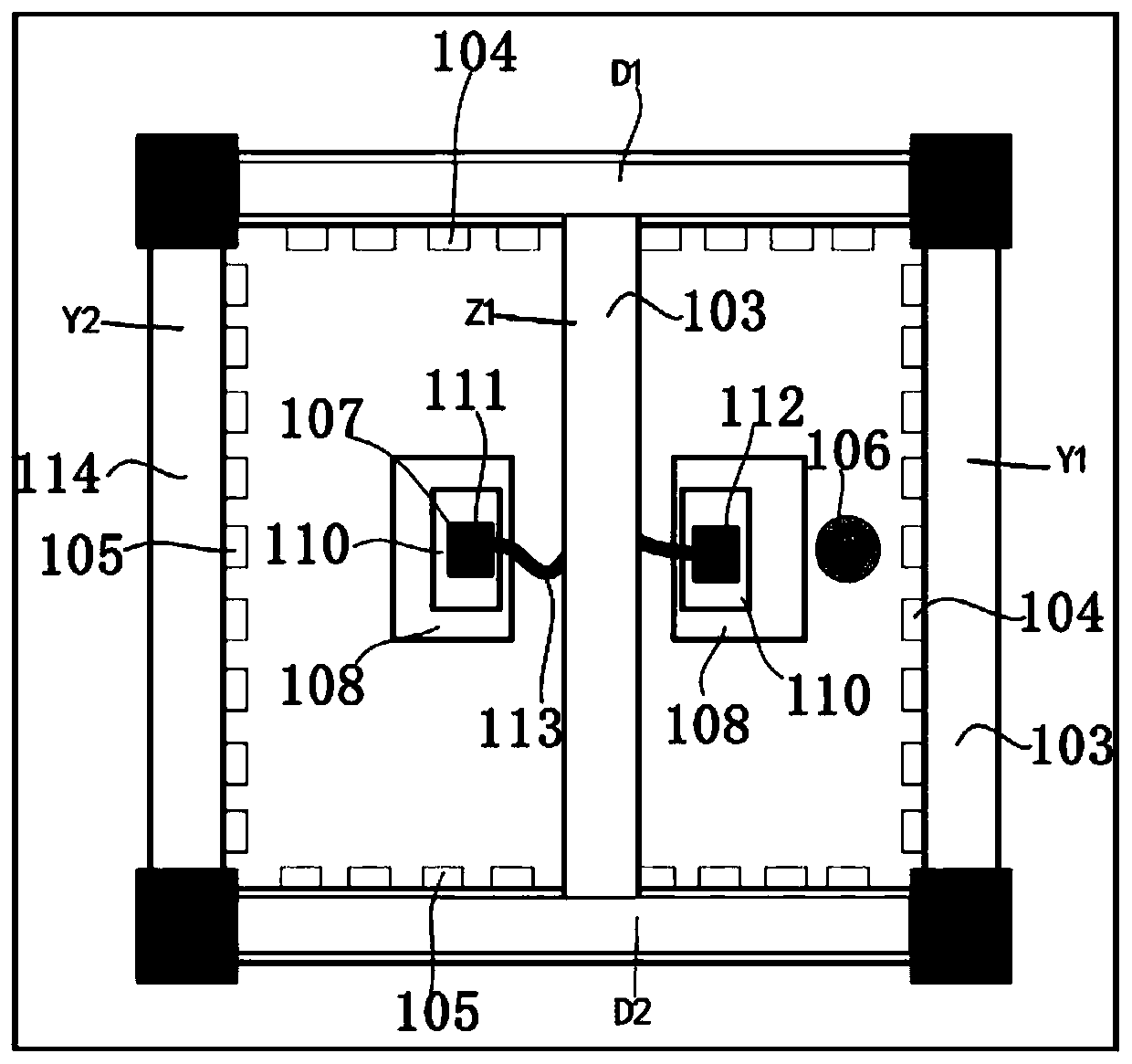
[0054] Such as Figure 4-6 As shown, the device can also realize two-dimensional lead arcing, and the steps are:

[0055] Step S21: After forming the first solder joint on the first pad 111, the ultrasonic sounding unit 103 emits ultrasonic waves through the ultrasonic transducer radiating end 104, in the resonance space between the ultrasonic transducer radiating end 104 and the reflecting unit 105 A sound pressure node is formed.

[0056] Step S22: During the rising process of the chopper 106, use the spatial fine-tuning of the radiation end 104 of the ultrasonic transducer located in the space and the corresponding reflection unit 105 to make the sound pressure node in the resonance space move freely within a certain range, and use the sound pressure The radiation force of the sound field at the node bends the lead 107 , thereby precisely controlling the location and angle of the inflection point 113 on the lead 107 .

[0057] Step S23: before the rivet 106 rises to the h...


PUM


Abstract

A three-dimensional rapid lead wire forming method, comprising the following steps: Step S1: After forming a first solder joint on a first pad, fixing the free end of the lead wire with a chopper, an ultrasonic sounding unit emits ultrasonic waves through the radiating end of an ultrasonic transducer, A sound pressure node is formed in the resonant space between the radiation end of the ultrasonic transducer and the reflection unit; Step S2: In the trajectory pre-designed by the hacking knife according to the computer program, use the radiation end of the ultrasonic transducer located in the space and the corresponding The spatial fine-tuning of the reflection unit enables the sound pressure node in the resonance space to move freely within a certain range, and the lead wire is bent by the sound field radiation force at the sound pressure node to precisely control the position and angle of the three-dimensional lead inflection point; Step S3: After the required folding point is bent and manufactured, the riving knife is lowered onto the second pad according to a predetermined trajectory, and the free end of the lead is welded to the second pad to complete the arc forming process of the lead.

Description

technical field [0001] The invention relates to the technical field of integrated circuit packaging, in particular to a method and device for three-dimensional rapid wire arc forming based on ultrasonic phased array manufacturing breakpoints. Background technique [0002] As a strategic, basic and leading industry in the national economy, the integrated circuit industry has a prominent core position in the field of information technology. Thermosonic wire bonding refers to the process of connecting the semiconductor chip welding area with the input and output leads of the microelectronic package or the metal wiring welding area on the substrate by means of the interaction of ultrasonic energy, pressure energy and thermal energy. , this process is a critical and time-consuming link in the IC manufacturing industry. [0003] Wire bonding is expected to play an important role in 3D stack packaging due to its advantages such as strong adaptability. In 3D stacked packaging, it ...

Claims


Application Information

Patent Timeline
Patent Type & Authority Patents(China)
IPC IPC(8): H01L21/60H01L21/607B23K1/00
CPCH01L24/85H01L24/48H01L24/78B23K1/00H01L2224/85205H01L2224/48247H01L2224/48091H01L2224/85181H01L2224/48095H01L2224/48465H01L2224/4809H01L2224/48227H01L2924/00
Inventor 陈云丁树权贺云波陈新刘强高健汪正平张胜辉杨海东
Owner GUANGDONG UNIV OF TECH
Learn More