Supercharge Your Innovation With Domain-Expert AI Agents!

Wetting roller

A technology of roller bodies and metal rollers, applied in shafts and bearings, guide/positioning/alignment devices, etc., can solve problems such as inconvenient installation, complex structure of guide rollers, no wetting function, etc. Good, good wetting performance

Inactive Publication Date: 2014-12-17
郑翔
View PDF1 Cites 3 Cited by
  • Summary
  • Abstract
  • Description
  • Claims
  • Application Information

AI Technical Summary

Problems solved by technology

The structure of the guide roller is complicated, it does not have a wetting function during the transmission process, and it is not convenient to install

Method used


Image

  • Wetting roller
  • Wetting roller

Examples


Embodiment Construction

[0014] In order to make the technical means, creative features, goals and effects achieved by the present invention easy to understand, the present invention will be further described below in conjunction with specific embodiments.

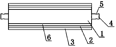
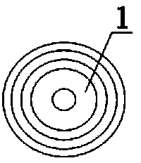
[0015] Such as figure 1 and figure 2 As shown, a wetting roller includes a roller body 1, a synthetic rubber layer 6 is arranged on the outer surface of the roller body 1, a fiber fabric layer 2 is covered on the synthetic rubber layer 6, and a flannelette is covered on the fiber fabric layer 2 The sleeve layer 3, the two ends of the roller body 1 are provided with a metal roller core 4, and the metal roller core 4 is provided with a mounting groove 5. The layers are connected, the fiber fabric layer 2 is connected with the synthetic rubber layer 6 through the glue layer, and the fleece cover layer 3 is connected with the fiber fabric layer 2 through the glue layer.

[0016] The wetting roller of the present invention uses the roller body 1 as ...


PUM


Abstract

The invention discloses a wetting roller, which comprises a roller body, a synthetic rubber layer is arranged on the external surface of the roller body, a synthetic rubber layer is coated with a fabric layer, the fabric layer is coated with a flannelette sleeve layer, the metal cores are arranged at two ends of the roller body, and two installation grooves are arranged on the metal core. The wetting roller has the advantages of simple structure, convenient usage, convenient installation and good wetting performance.

Description

technical field [0001] The invention relates to a roll, in particular to a dampening roll. Background technique [0002] In the prior art, such as patent ZL200910116096.7 discloses a guide roller in the guide device that guides and supports the rolled piece to enter the rolling groove stably and accurately for rolling; at least one end surface of the two roller end surfaces of the guide roller is There are recesses or protrusions on the top of the guide roller, and a guiding and rotating device is provided on the side of the guide roller. The guiding and rotating device provides fluid power to point to the region of the recess or protrusion and push the guide roller to rotate, and the direction of rotation of the guide roller is in line with the direction of the rolling piece. unanimous. The guide roller has a complex structure, does not have a wetting function during transmission, and is inconvenient to install. Contents of the invention [0003] Aiming at the deficienc...

Claims


Application Information

Patent Timeline
Patent Type & Authority Applications(China)
IPC IPC(8): B21B39/16F16C13/00
Inventor 郑翔
Owner 郑翔
Features
  • R&D
  • Intellectual Property
  • Life Sciences
  • Materials
  • Tech Scout
  • Unparalleled Data Quality
  • Higher Quality Content
  • 60% Fewer Hallucinations
Learn More