Sandblaster with pipe automatically wound

A sandblaster, automatic technology, used in pipeline laying and maintenance, pipes/pipe joints/fittings, machinery and equipment, etc., can solve problems such as low work efficiency and poor product quality, and achieve the goal of improving product quality and improving work efficiency. Effect

Inactive Publication Date: 2014-12-17
天津市冠成钢品制造有限公司
View PDF0 Cites 1 Cited by
  • Summary
  • Abstract
  • Description
  • Claims
  • Application Information

AI Technical Summary

Problems solved by technology

However, this kind of equipment needs to be manually collected when the sand and rubber pipe is withdrawn while blowing

Method used


Image

  • Sandblaster with pipe automatically wound

Examples


Embodiment Construction

[0015] In order to enable those skilled in the art to better understand the technical solutions of the present invention, the present invention will be further described in detail below in conjunction with the accompanying drawings and preferred embodiments.

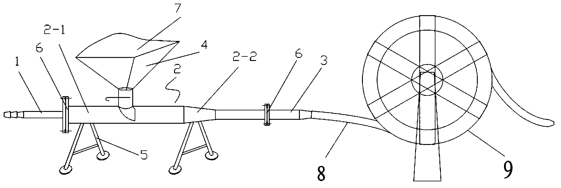
[0016] As shown in the figure, a sand blaster with automatic pipe collection in the present invention is mainly composed of an air inlet pipe 1, a sand storage pipe 2 and a sand discharge pipe 3 which are sequentially connected by a flange 6, and the upper part of the sand storage pipe is fixed vertically. The sand feeding hopper 4 connected with it has a support leg 5 fixedly connected to the lower part of the sand storage pipe, and the sand outlet pipe is connected with a sand outlet rubber hose 8, and the sand outlet rubber hose is coiled on a tube collection disk 9 driven by a motor.

[0017] When in use, firstly block a part of the front end of the jacking pipe, the air inlet pipe is connected with the air pump throu...


PUM


Abstract

The invention relates to a sand blasting tool, in particular to a sandblaster with a pipe automatically wound. The sandblaster with the pipe automatically wound is applied to pipe jacking and heating pipeline filling fixtures in heat pipelines laid based on the non-excavation technology, and is mainly composed of an air inlet pipe, a sand storage pipe and a sand outlet pipe, the air inlet pipe, the sand storage pipe and the sand outlet pipe are connected in sequence through flanges, the upper portion of the sand storage pipe is vertically and fixedly connected with a sand inlet hopper communicated with the sand storage pipe, the lower portion of the sand storage pipe is fixedly connected with supporting legs, the sand outlet pipe is connected with a sand outlet rubber pipe, and the sand outlet rubber pipe is wound on a pipe winding reel driven by a motor. Due to the fact that the sand outlet pipe is designed to be connected with the sand outlet rubber pipe, the sand outlet rubber pipe is wound on the pipe winding reel driven by the motor, the pipe winding reel is driven by the motor to automatically wind the pipe, work efficiency is improved, the speed is constant and can be regulated, and product quality is improved.

Description

technical field [0001] The invention relates to a sandblasting tool, in particular to a sandblasting device used for automatic collection of pipe jacking and thermal pipeline filling fixtures in laying heating network pipelines using trenchless technology. Background technique [0002] The heat network is composed of heat transmission trunk lines, heat distribution trunk lines, and branch lines. The heat transmission main line is drawn from the heat source, and generally does not connect to the branch line; the heat distribution main line is directly connected to the heat transmission main line or directly from the heat source, and heat is supplied to the user through the heat distribution branch line. [0003] The layout of the heating network is mainly determined according to the distribution of urban heat load, the status quo of the block, the development plan, and the geological and topographical conditions, etc., and is generally arranged in a branch shape. When heat i...

Claims


Application Information

Patent Timeline
IPC IPC(8): F16L1/06F16L1/028
CPCF16L1/06F16L1/028
Inventor 齐永杰
Owner 天津市冠成钢品制造有限公司
Why Eureka
Try Eureka