
Touch control panel

A technology of touch panel and touch area, which is applied in the direction of instruments, electrical digital data processing, input/output process of data processing, etc., and can solve problems such as poor electrostatic discharge effect

Active Publication Date: 2014-12-17
AU OPTRONICS CORP
View PDF6 Cites 7 Cited by
  • Summary
  • Abstract
  • Description
  • Claims
  • Application Information

AI Technical Summary

Problems solved by technology

However, when the touch panel 8 has not yet become a system with a casing in the process, the single ground wire 81 is as Figure 8 The shown is in the off-circuit state of large impedance, and the electrostatic discharge effect is not good

Method used


Image

  • Touch control panel
  • Touch control panel
  • Touch control panel

Examples


Embodiment Construction

[0041] The following describes the detailed features of the present invention in the implementation manner, and its content is enough to make any person skilled in the art understand the technical content of the present invention and implement it accordingly, and according to the content disclosed in this specification, the patent scope of the application and the accompanying drawings, any of the present invention Those skilled in the art can easily understand the related objects and advantages of the present invention. The following examples further illustrate aspects of the present invention, but do not limit the scope of the present invention in any way.

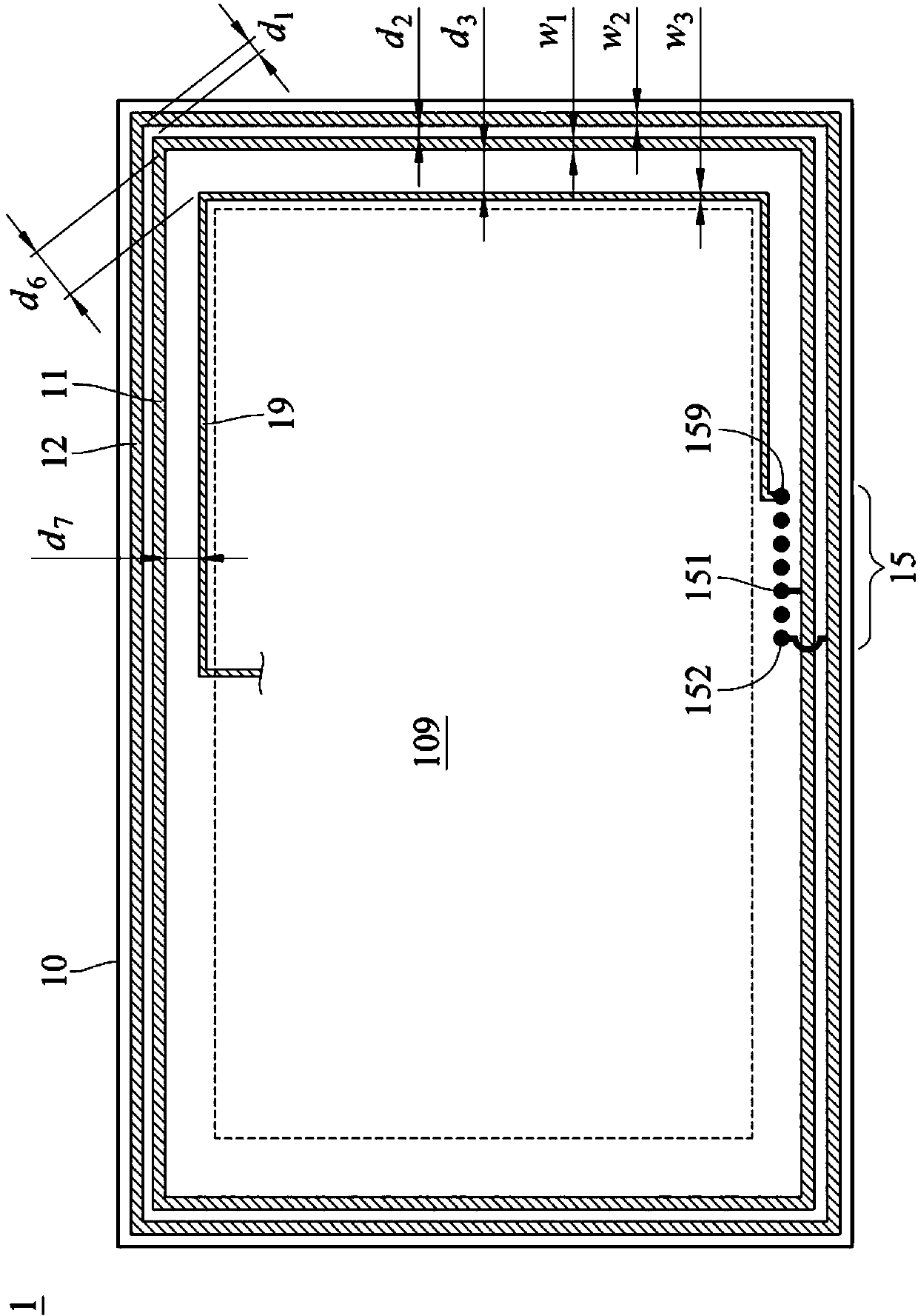
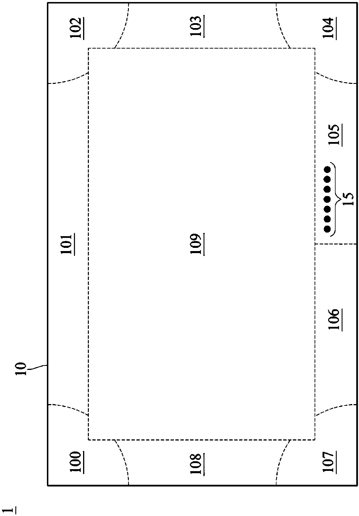
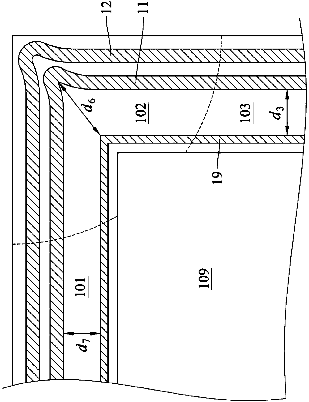
[0042] See figure 1 , shows a touch panel 1 according to an embodiment of the present invention. In an embodiment, the touch panel 1 includes a substrate 10 , a first ground wire 11 and a second ground wire 12 . A touch area 109 is defined in the center of the substrate 10 , and the control panel 1 serves as an input / o...


PUM


Abstract

The invention discloses a touch control panel comprising a base plate, a first ground lead and a second ground lead. The base plate is provided with a touch control area and a peripheral area surrounding the touch control area; the two ground leads are both arranged on the peripheral area and connected in a non-electrical way; and a distance between the two ground leads is smaller than a first threshold value.

Description

technical field [0001] The present invention relates to touch technology, in particular to protection against electrostatic discharge (ESD) in touch panel technology. Background technique [0002] Any conductor on which static charges may inevitably accumulate or flow during touch panel processing and use. by Figure 8 For example, a typical touch panel 8 includes a substrate 80 and conductors such as a ground line 81 , a plurality of drive lines 89d (drive lines), and a plurality of scan lines 89s (sensor lines). The driving line 89d and the scanning line 89s are intersected on the touch area 809 of the substrate 80 and connected to a plurality of bonding pads 85 (bonding pads, commonly known as golden fingers). The ground line 81 is disposed on the substrate 81 around the peripheral area of ​​the touch area 809, and the ground line disposed between the drive lines 89d, the scan lines 89s, and between the two for isolating signals is not shown in the figure. Figure 8 . T...

Claims


Application Information

Patent Timeline
IPC IPC(8): G06F3/041
Inventor 庄文奇杨佳峰
Owner AU OPTRONICS CORP
Learn More