Supercharge Your Innovation With Domain-Expert AI Agents!

Switch box for stable installation of cables

A switch box and cable technology, applied in the cooling/ventilation of substation/switchgear, busbar/line layout, etc., can solve the problems of messy lines in the cable room, inconvenient maintenance, etc., and save time for finding lines and arranging lines Neat and easy maintenance

Active Publication Date: 2016-05-18
CHENGDU ZHIRONG ZHICHUANG INTPROP MANAGEMENT CO LTD
View PDF5 Cites 0 Cited by
  • Summary
  • Abstract
  • Description
  • Claims
  • Application Information

AI Technical Summary

Problems solved by technology

[0005] The purpose of the present invention is to solve the problem that the cables in the cable room are messy and inconvenient to maintain in the prior art, and to provide a switch box suitable for the stable installation of cables, which is easy to arrange, has good stability after arrangement, and is easy to maintain

Method used


Image

  • Switch box for stable installation of cables
  • Switch box for stable installation of cables
  • Switch box for stable installation of cables

Examples


Embodiment 1

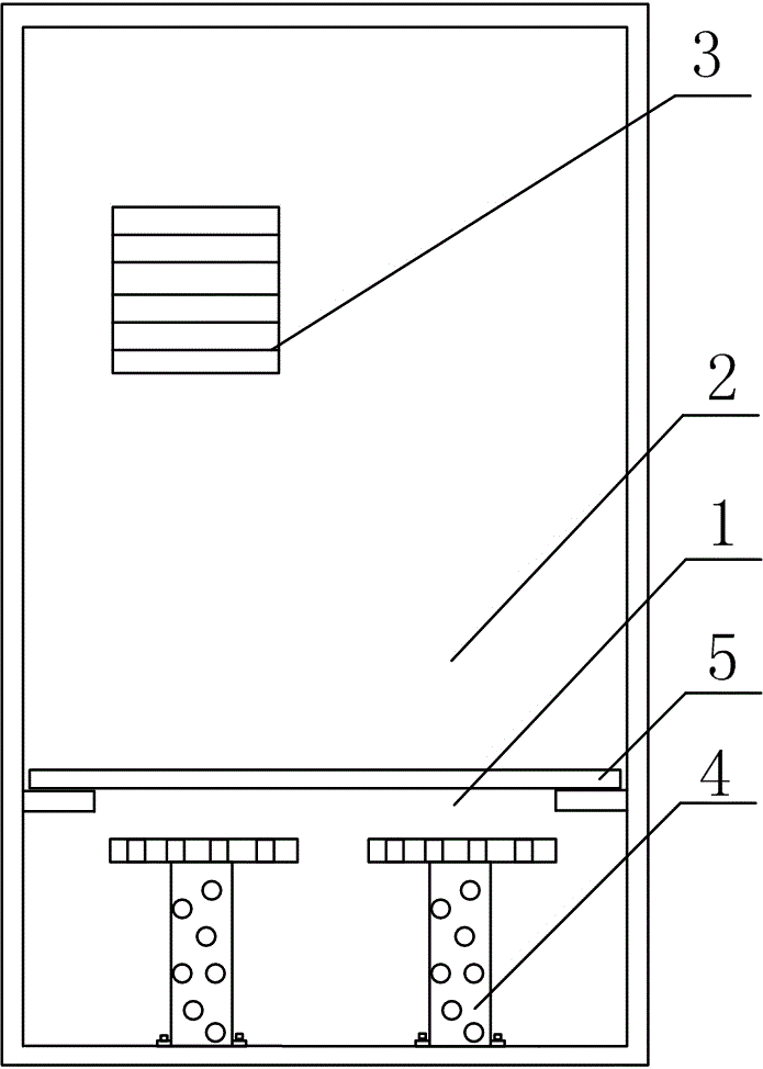
[0026] Switch box for stable installation of cables, e.g. figure 1 As shown, it includes the cable room 1, the installation room 2, the air vent 3 and the hub 4. The specific arrangement of the above components and the connection relationship between them are as follows:

[0027] The cable room 1 is installed in the underground part, the installation room 2 is arranged above the cable room 1, and the cable room 1 and the installation room 2 are provided with air vents 3, and the bottom end of the hub 4 is fixed on the On the bottom of the cable compartment 1, such as figure 1 shown.

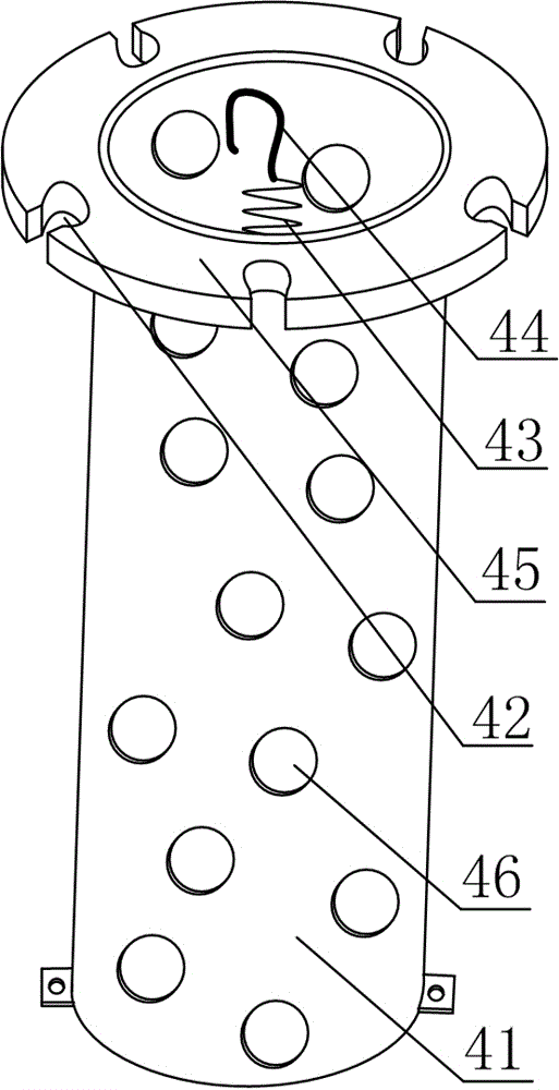
[0028] Such as figure 2 As shown, the hub 4 includes a cylindrical cylinder 41 whose bottom end is fixed on the bottom surface of the cable chamber 1 and is hollow inside, and a cable slot 42 arranged at the upper end of the cylinder 41, and one end is fixed at the hollow position of the cylinder 41 The spring 43 at the place is fixed on the hook 44 at the other end of the spring 43;

[0029...

Embodiment 2

[0032] The difference between this embodiment and Embodiment 1 is that the structure at the position of the wire clamping slot 42 is optimized, and the specific settings are as follows:

[0033] The upper end of the cylindrical body 41 is provided with a ring-shaped connector 45, and the clamping groove 42 is evenly distributed around the ring-shaped connector 45, such as figure 2 shown.

[0034] After all the redundant cables are wound on the cylinder 41, one end extending to the installation chamber 2 is snapped into the wire clamping groove 42, because it is not sure whether there is a wire clamping groove 42 at the position where the cables finally protrude from the cylinder 41 exist, so in this embodiment the number of clamping grooves 42 is multiple, evenly distributed around the cylinder 41, such as figure 2 shown.

Embodiment 3

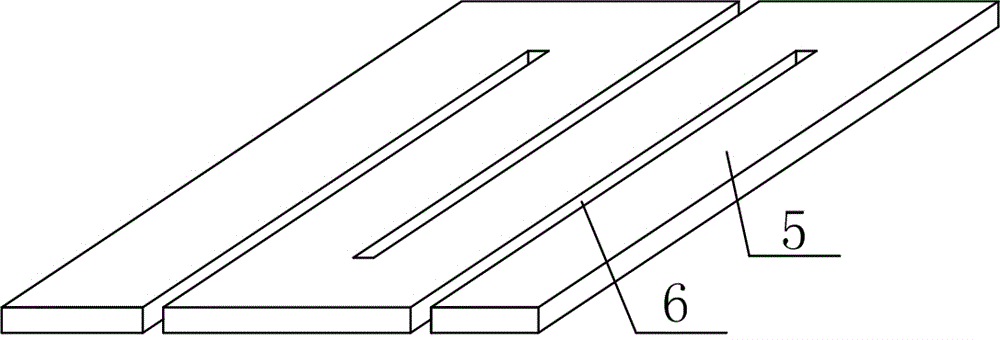
[0036] In this embodiment, a detachable partition 5 is added on the basis of embodiment 2, and the specific structure of the line through hole 6 on the detachable partition 5 is limited. The specific setting method is as follows:

[0037] A detachable partition 5 is also provided between the cable chamber 1 and the installation chamber 2, and a line through hole 6 is arranged on the detachable partition 5; one end of the line through hole 6 is an open structure, such as image 3 shown. With this setting, the detachable partition 5 can be effectively removed without moving the connection relationship of the cables during later maintenance of the cables, making maintenance more convenient.


PUM


Abstract

The invention discloses a switch box applicable to stably installing cables, for mainly solving the problem that in the prior art cables in a cable chamber are disorder and inconvenient to maintain. The switch box comprises a cable chamber installed underground, an installing chamber arranged on the cable chamber and air vents formed on the cable chamber and the installing chamber, and is characterized in that a concentrator is fixed on the bottom surface of the cable chamber; the concentrator comprises a cylindrical barrel with a bottom end fixed on the bottom surface of the cable chamber and a hollow internal part, a cable clamping groove arranged at the upper end of the barrel, a spring with one end fixed to the hollow part of the barrel, and a hook fixed to the other end of the spring; when the spring is in a common state, the top end of the hook is lower than the upper surface of the barrel. The switch box has the advantages of being convenient to tidy up cables, good in stability after tidying, convenient to maintain and simple to operate.

Description

technical field [0001] The invention relates to a switch box, in particular to a switch box suitable for stable installation of cables. Background technique [0002] The switch cabinet is a kind of electrical equipment. The outside line of the switch cabinet first enters the main control switch in the cabinet, and then enters the sub-control switch, and each branch is set according to its needs. Such as instruments, automatic controls, motor magnetic switches, various AC contactors, etc., some also have high-voltage room and low-voltage room switch boxes, high-voltage busbars, such as power plants, etc. load shedding. [0003] The main function of the switch box is to open and close, control and protect electrical equipment during the process of power generation, transmission, distribution and power conversion in the power system. The components in the switch box are mainly composed of circuit breakers, isolating switches, load switches, operating mechanisms, transformers ...

Claims


Application Information

Patent Timeline
Patent Type & Authority Patents(China)
IPC IPC(8): H02B1/20H02B1/56
Inventor 李胜峰
Owner CHENGDU ZHIRONG ZHICHUANG INTPROP MANAGEMENT CO LTD
Features
  • R&D
  • Intellectual Property
  • Life Sciences
  • Materials
  • Tech Scout
  • Unparalleled Data Quality
  • Higher Quality Content
  • 60% Fewer Hallucinations
Learn More