Slow start circuit and optical module with same

A technology of slow start circuit and current discharge, which is applied in the field of optical communication, can solve the problems of power supply shock, optical module electrification, and inability to start the optical module with delay, so as to avoid power supply and current shock

Active Publication Date: 2014-12-17
INNOLIGHT TECHNOLOGY (SUZHOU) LTD
View PDF5 Cites 4 Cited by
  • Summary
  • Abstract
  • Description
  • Claims
  • Application Information

AI Technical Summary

Problems solved by technology

These circuits can effectively suppress the inrush current during hot insertion or cold start of the module, but the common defect of the two is that during the process of pulling out the optical module, due to the multiple mechanical vibrations of the power signal connector, the optical module will be short-circuited. During the period of time, there are several repeated on-off processes between the power supply and the power supply. In this process, the optical module is still charged during the short interval between the optical module and the power supply. In the process of instantaneous connection with the power supply, these chips and delay circuits cannot play the role of delaying the start of the optical module, and the optical module will respond and work in time, causing an impact on the power supply

Method used


Image

  • Slow start circuit and optical module with same
  • Slow start circuit and optical module with same

Examples


Embodiment Construction

[0019] The present invention will be described in detail below in conjunction with specific embodiments shown in the accompanying drawings. However, these embodiments do not limit the present invention, and any structural, method, or functional changes made by those skilled in the art according to these embodiments are included in the protection scope of the present invention.

[0020] It should be understood that although the terms first, second, etc. may be used herein to describe various elements or structures, these described objects should not be limited by these terms. These terms are only used to distinguish these described objects from one another. For example, the first current limiting resistor can be called the second current limiting resistor, and similarly the second current limiting resistor can also be called the first current limiting resistor, which does not depart from the protection scope of the present invention.

[0021] In different implementations / embod...


PUM


Abstract

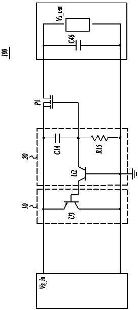
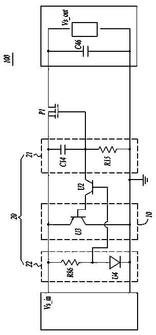
The invention discloses a slow start circuit and an optical module with the same. The slow start circuit provided with a power source input end and a load output end comprises a switch device and a switch voltage adjuster and current discharge channel connected therewith. The switch device is in series connection between the power source input end and the load output end. The switch voltage adjuster controls opening of the current discharge channel during disconnection of the power source input end so as to enable the load output end to discharge electricity, and controls closing of the current discharge channel during power-on of the power source input end. Due to arrangement of the current discharge channel in the slow start circuit, the load output end can discharge electricity by the current discharge channel through control of the switch voltage adjuster when the power source input end is disconnected, so that the switch device does not respond timely to be connected in the ephemeral power-on process, caused by mechanical dither, of the slow start circuit and the power source input end, power supply to the load output end is avoided, and further, current impact on a power source is avoided.

Description

technical field [0001] The invention belongs to the technical field of optical communication, and in particular relates to a slow start circuit and an optical module with the slow start circuit. Background technique [0002] Optical communication technology is playing an increasingly important role in modern society. In the actual application environment, in order to meet the needs of multi-channel data transmission, the same host or line card is usually equipped with multiple optical modules, and the host uses the same DC power supply Provide power to each optical module. In order to ensure the stability of optical communication, when one or more optical modules are inserted or pulled out, it is required that no current impact will be generated on the power supply, so as to avoid affecting other optical modules that are running, or even cause communication link failure. Fault. [0003] In the prior art, two methods are usually adopted to deal with the above problems. One...

Claims


Application Information

Patent Timeline
Patent Type & Authority Applications(China)
IPC IPC(8): H03K17/28
Inventor 王祥忠
Owner INNOLIGHT TECHNOLOGY (SUZHOU) LTD
Why Eureka
Try Eureka