
Monitoring pick-up device and cooling and dehumidifying method thereof

A monitoring camera, cooling and dehumidification technology, applied in the direction of image communication, TV, color TV components, etc., to achieve timely dehumidification, reduce impact, and good heat dissipation

Inactive Publication Date: 2014-12-17
SHENZHEN INFINOVA
View PDF10 Cites 9 Cited by
  • Summary
  • Abstract
  • Description
  • Claims
  • Application Information

AI Technical Summary

Problems solved by technology

[0003] The technical problem to be solved by the present invention is to provide a monitoring camera device and its cooling and dehumidification method to solve the phenomenon that the existing monitoring camera device has poor cooling and dehumidification effect, resulting in blurred monitoring vision

Method used


Image

  • Monitoring pick-up device and cooling and dehumidifying method thereof
  • Monitoring pick-up device and cooling and dehumidifying method thereof
  • Monitoring pick-up device and cooling and dehumidifying method thereof

Examples


Embodiment 1

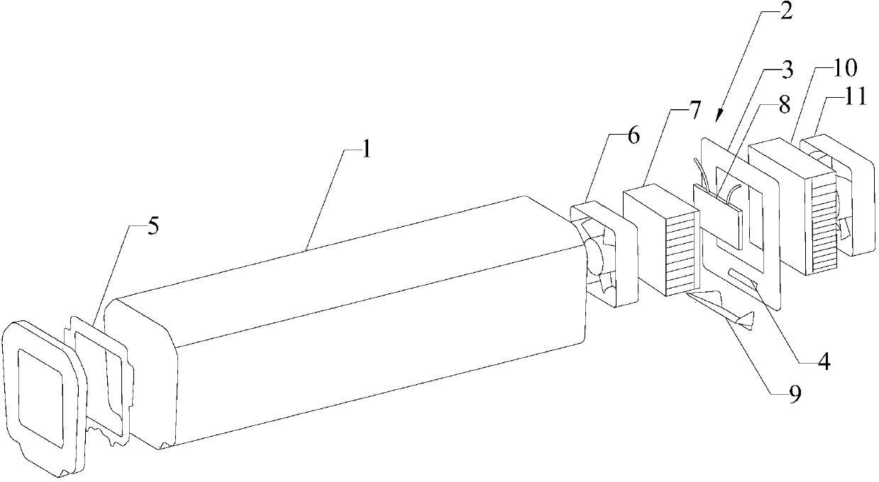
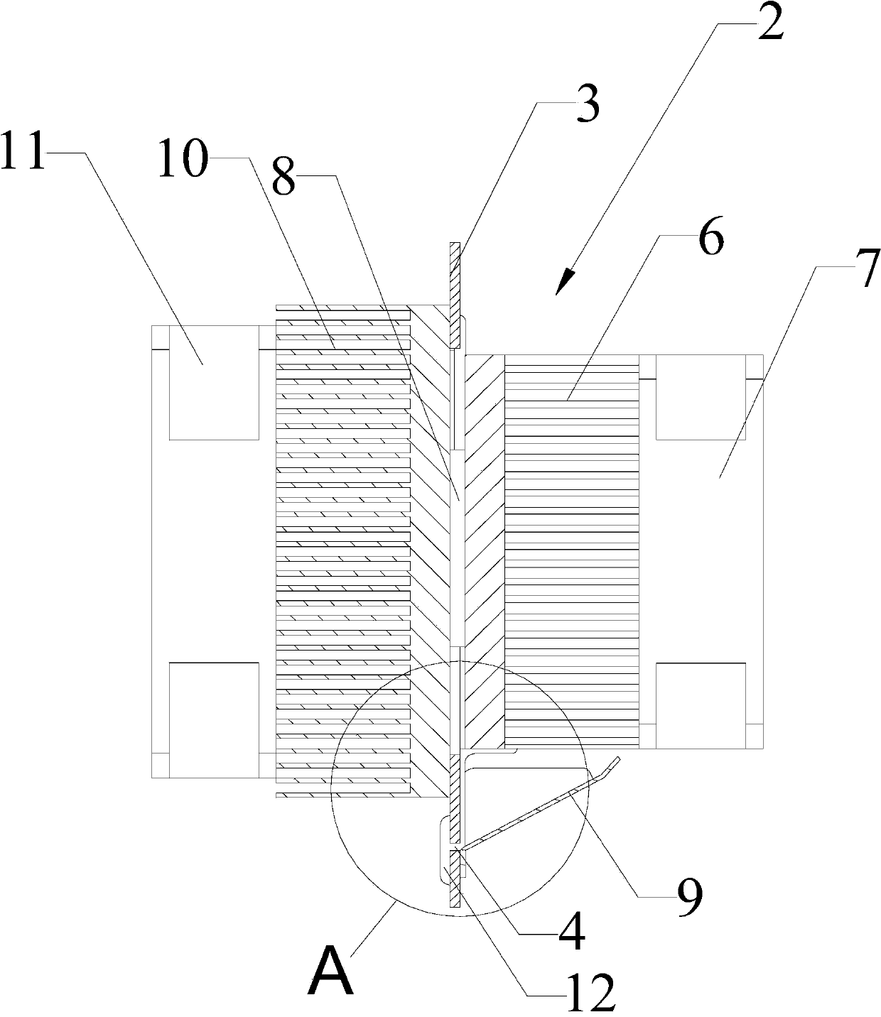
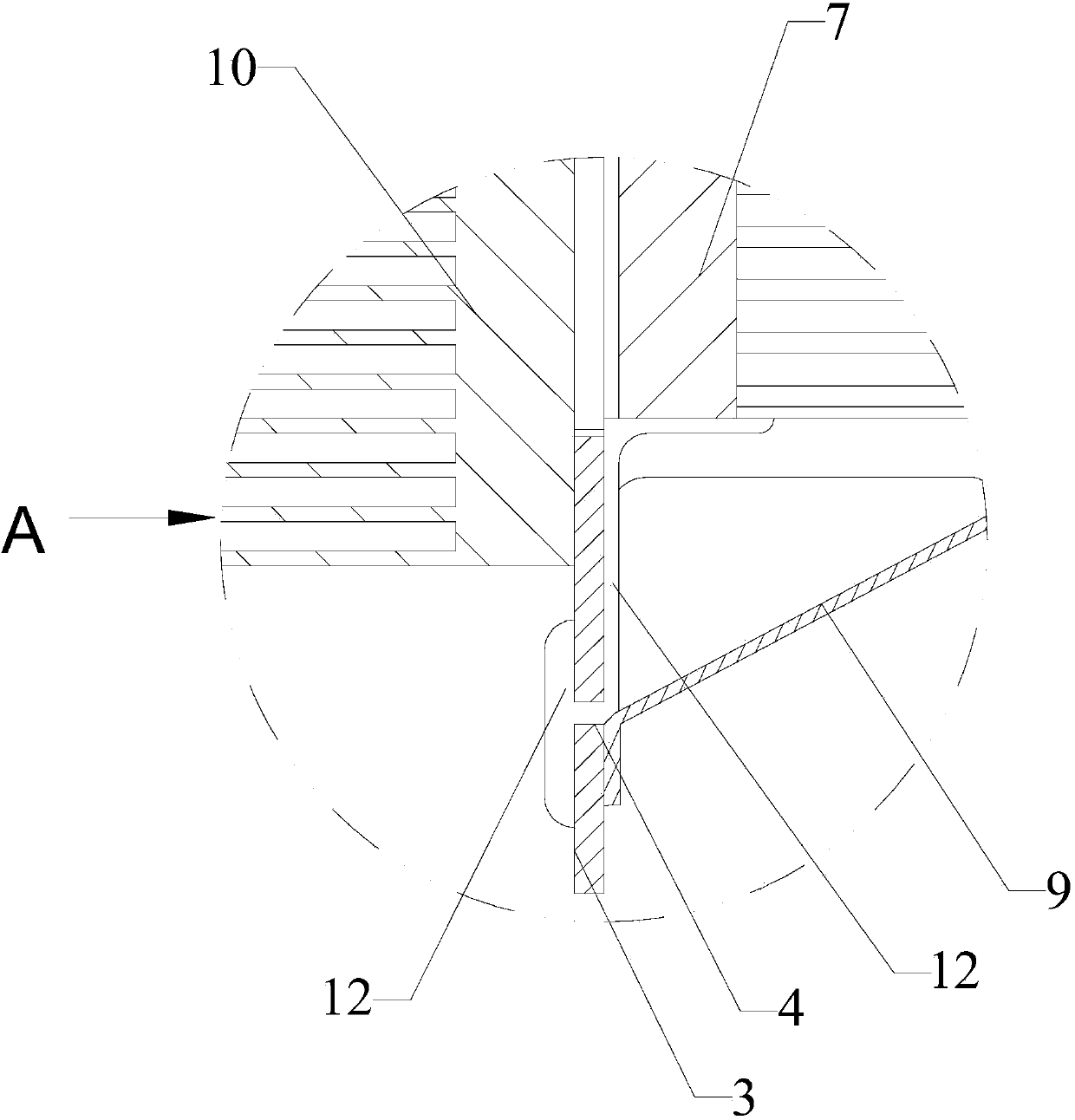
[0060] The control board 5 is fixed on the window front shell, the window front shell is fixed on the front end of the protective frame 1, the semiconductor cooling fin 8 is placed between the first heat sink and the second heat sink, and the first heat sink and the second heat sink After being connected together with screws, the first fan 6 is fixed on the first heat sink, and the second fan 11 is fixed on the second fan heat sink to form a cooling / dehumidifying core module; the cooling / dehumidifying core module is fixed on the On the back cover 3 of the protection frame 1, the water receiving tank 9 is fixed below the back cover 3, and the position above the corresponding water receiving tank 9 is provided with a water guide hole 4 on the back cover 3, and the inside and outside of the water guide hole 4 are all coated with There is a polymer water-absorbing resin, and the bottom of the first radiator 7 extends to the position of the water guide hole 4 and is also coated with...

Embodiment 2

[0062] The intelligent cooling process includes: when the temperature inside the protective frame 1 exceeds the set value, the control board 5 starts the semiconductor cooling chip 8, the first fan 6 and the second fan 11 to work, and the low temperature of the cooling surface of the semiconductor cooling chip 8 is conducted to the first On the heat sink, the cold air on the first heat sink is extracted and blown into the cavity of the protection frame 1 by the first fan 6, thereby achieving the purpose of reducing the temperature in the protection frame 1; On the heat sink, the heat is dissipated into the air by the second fan 11 to achieve the effect of circulation and continuous cooling.

[0063] The intelligent dehumidification process includes: using the air at different temperatures, the water content of the same humidity value is different (the higher the temperature, the greater the water content), when the humidity RH% in the protection frame 1 exceeds the set value, t...


PUM


Abstract

The invention provides a monitoring pick-up device and a cooling and dehumidifying method thereof. The device comprises a monitoring camera protection frame and a cooling and dehumidifying device; a water guide hole is formed in the bottom of the rear cover of the protection frame; the control panel of the cooling and dehumidifying device is fixedly arranged on the protection frame; the rear cover is provided with a hollow part in which a semiconductor chilling plate is corresponding arranged; a first radiator is fixedly connected to one side, facing the protection frame, of the semiconductor chilling plate; a first fan is fixedly connected with the first radiator; a second radiator is fixedly connected to the outer side of the semiconductor chilling plate; a second fan is fixedly connected with the second radiator; a water receiving tank is arranged on the inner side of the rear cover and located under the water guide hole; a water absorbing material is paved in and at the periphery of the water guide hole. The monitoring pick-up device has the advantages of high cooling and dehumidification effect, and low operation noise, and can be protected against the influence of environmental factors and operates well.

Description

technical field [0001] The invention relates to the field of monitoring cameras, in particular to a monitoring camera device and a cooling and dehumidification method thereof. Background technique [0002] The monitoring cameras of the prior art are generally a method of directly installing a fan in the protective frame of the monitoring camera to achieve dehumidification and cooling. However, the ideal heat dissipation and dehumidification standard cannot be achieved through simple fan settings. In humid environments such as rainy weather, the temperature difference between the inside and outside of the goggle caused by the heating phenomenon of the surveillance camera due to long-term use will still lead to blurring of the surveillance camera. The fever phenomenon has not been well resolved. Therefore, it is necessary to provide a monitoring camera device and a cooling and dehumidification method thereof, which can achieve a good cooling and dehumidification effect. Con...

Claims


Application Information

Patent Timeline
Patent Type & Authority Applications(China)
IPC IPC(8): H04N5/225H04N7/18
Inventor 程时毅陈洪春张伟胡雪峰张超吴莹莹田颖
Owner SHENZHEN INFINOVA
Learn More