Bidirectional motion estimating method and video frame rate up-converting method and system

A two-way motion estimation and motion vector technology, applied in digital video signal modification, image communication, electrical components, etc., can solve the problem that the motion vector cannot completely and accurately reflect the motion state of the moving object

Active Publication Date: 2014-12-17
SUZHOU KEDA TECH +2
View PDF8 Cites 26 Cited by
  • Summary
  • Abstract
  • Description
  • Claims
  • Application Information

AI Technical Summary

Problems solved by technology

[0005] For this reason, the technical problem to be solved by the present invention is that the motion vector obtained by the bidirectional motion estimation method based on unidirectional block matching search used for video frame rate up-conversion in the prior art cannot completely and accurately reflect the motion state of the moving object, Thereby, a two-way motion estimation method and a video frame rate up-conversion method and system are proposed

Method used


Image

  • Bidirectional motion estimating method and video frame rate up-converting method and system
  • Bidirectional motion estimating method and video frame rate up-converting method and system
  • Bidirectional motion estimating method and video frame rate up-converting method and system

Examples


Embodiment 1

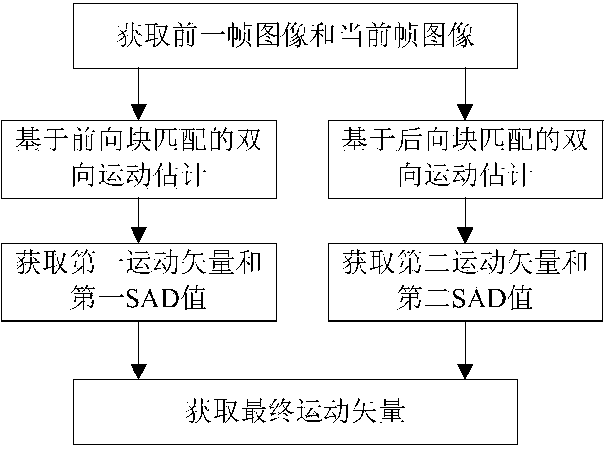
[0085] This embodiment provides a two-way motion estimation method, such as figure 1 shown, including the following steps:

[0086] S1: Read the previous frame image pre_img and the current frame image cur_img.

[0087] S2: Perform bidirectional motion estimation based on forward block matching according to the previous frame image and the current frame image, and obtain the first SAD value and the corresponding first motion vector, the first SAD value is a bidirectional motion based on forward block matching Estimate the smallest SAD value among all obtained SAD values.

[0088] Step S2 specifically includes the following steps:

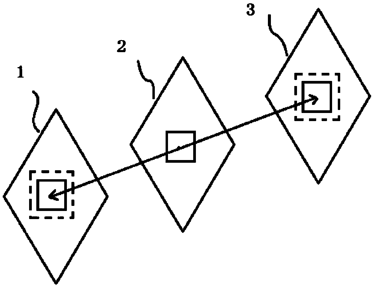
[0089] S21: Take out a 4x4 image block in the previous frame image pre_img, and perform similar block matching within the search range of + / -8 pixels in the current frame image cur_img. The search range is based on the coordinates of the upper left corner of the current image block. There are 8 pixels at the top, bottom, left, and right of the ce...

Embodiment 2

[0127] This embodiment provides a two-way motion estimation method. Embodiment 2 is a modification based on Embodiment 1. It differs from Embodiment 1 in that a is calculated in step S4 1 and a 2 the process of.

[0128] In step S4 of this embodiment, including calculating a 1 and a 2 The process is as follows:

[0129] When SAD 1 = SAD 2 = 0, a 1 =a 2 = 0.5;

[0130] When SAD 1 ≠ and SAD 2 ≠0, a 1 =1-SAD 1 2 / (SAD 1 2 +SAD 2 2 ),a 2 =1-SAD 2 2 / (SAD 1 2 +SAD 2 2 );

[0131] of which SAD 1 is the first SAD value, SAD 2 is the second SAD value.

[0132] In the bidirectional motion estimation method described in this embodiment, after acquiring the previous frame image and the current frame image, respectively perform bidirectional motion estimation based on forward block matching and bidirectional motion estimation based on backward block matching, and then obtain The minimum SAD value and the corresponding motion vector are obtained to obtain the fi...

Embodiment 3

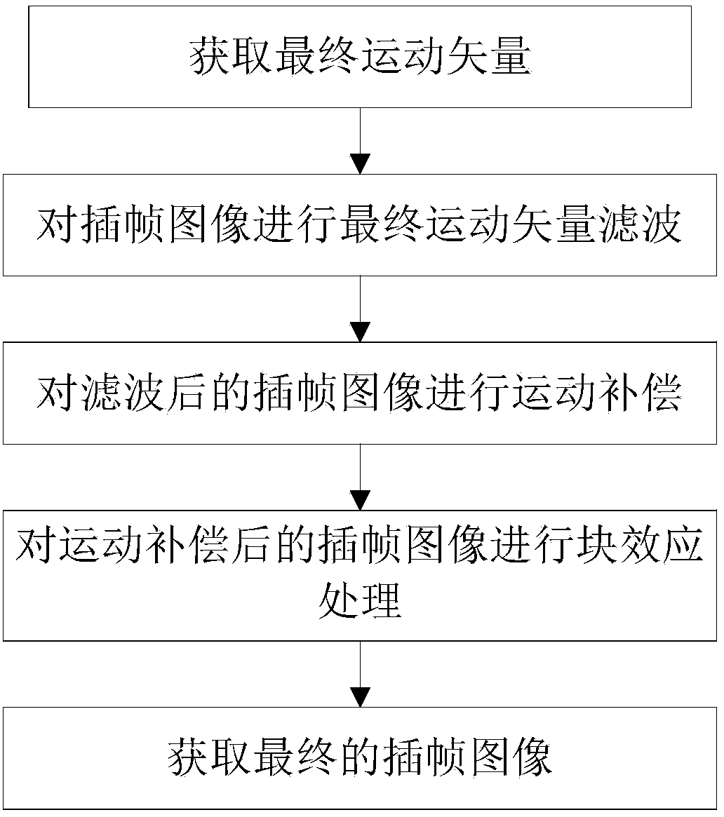
[0134] This embodiment provides a method for video frame rate up-conversion, such as image 3 shown, including the following steps:

[0135] T1: Obtain the final motion vector (mvx, mvy) by using the two-way motion estimation method described in Embodiment 1 or Embodiment 2. Assuming that the coordinates of the current image block in the interpolation image interp_img are (w, h), a total of 9 groups of final motion vectors (mvx1~mvx9, mvy1~mvy9 ). These 9 groups of final motion vectors are sequentially used as the motion vectors of the current image block.

[0136] T2: Perform final motion vector filtering on the interpolated frame image. Obtain the coordinates (w-mvx1~mvx9, h-mvx1~mvx9) of the current image block in the previous frame image pre_img and the current frame image cur_img according to the value of the motion vector, (w+mvx1~mvx9, h+mvx1~mvx9), And calculate the SAD values ​​​​of these two image blocks. If there is a fractional part in the coordinates of the prev...


PUM


Abstract

The invention provides a bidirectional motion estimating method and system. The method comprises, after a prior frame image and a current frame image are obtained, performing bidirectional motion estimation based on forward block matching and backward block matching respectively; then according to the minimum SAD (sum of absolute difference) value and the corresponding motion vector which are obtained respectively, obtaining a final motion vector, wherein the obtained final motion vector can accurately describe the motion status of a moving object and accordingly solve the confusion between the moving object and the background due to inaccuracy of the motion vector. The invention also provides a video frame rate up-converting method and system. The method comprises obtaining the final motion vector according to the bidirectional motion estimating method and system and then performing motion vector filtering, motion compensation and blocking effect treatment; the finally obtained interpolated frames can eliminate confusion between the moving object and the background and blocking effects, improves the image quality of interpolated images, reduces the problems such as smoothness and continuity of video images and improves the visual effects of videos.

Description

technical field [0001] The invention relates to the field of video image processing, in particular to a bidirectional motion estimation method and a video frame rate up-conversion method and system. Background technique [0002] Due to the rapid development of digital image processing technology and multimedia information technology in recent years, high-definition video conferencing is widely used in various venues, especially represented by 1080p high-definition. 1080p high-definition technology brings high-quality picture quality, but at the same time, due to the high-quality requirements, the problem of network bandwidth limitation is more prominent in the process of video information transmission. Under the limited network bandwidth, the video frame rate is forced to Reduce, so that when the entire video stream is played, the picture will not be smooth, especially the movement of moving objects is not continuous. In order to solve this problem, we need to introduce a v...

Claims


Application Information

Patent Timeline
Patent Type & Authority Applications(China)
IPC IPC(8): H04N19/577H04N19/86H04N19/132H04N19/513H04N19/59
Inventor 熊超章勇曹李军陈卫东
Owner SUZHOU KEDA TECH
Why Eureka
Try Eureka