Heat dissipation assembly structure

A technology for assembling structures and heat dissipation components, which is applied in the direction of cooling/ventilation/heating transformation, etc., and can solve problems such as damage to electronic components, decreased performance, and increased heat dissipation costs

Inactive Publication Date: 2014-12-17
WISTRON NEWEB
View PDF5 Cites 6 Cited by
  • Summary
  • Abstract
  • Description
  • Claims
  • Application Information

AI Technical Summary

Problems solved by technology

Because the performance of electronic components with high temperature will drop suddenly, and may cause damage to electronic components, the problem of heat dissipation has become an important issue
[0003] For electronic components with high power consumption, the heat dissipation structure usually needs to be more complicated to enhance its heat dissipation effect
However, the fixed components required by the complex heat dissipation structure also increase, which also increases the cost of heat dissipation, and the complex heat dissipation structure may also cause uneven heat dissipation, resulting in waste of heat dissipation materials

Method used


Image

  • Heat dissipation assembly structure
  • Heat dissipation assembly structure
  • Heat dissipation assembly structure

Examples


Embodiment Construction

[0030] A number of implementations of the present invention will be disclosed below with the accompanying drawings. For the sake of clarity, many practical details will be described together in the following description. It should be understood, however, that these practical details should not be used to limit the invention. That is, in some embodiments of the present invention, these practical details are unnecessary. In addition, for the sake of simplifying the drawings, some conventional structures and elements will be shown in a simple and schematic way in the drawings.

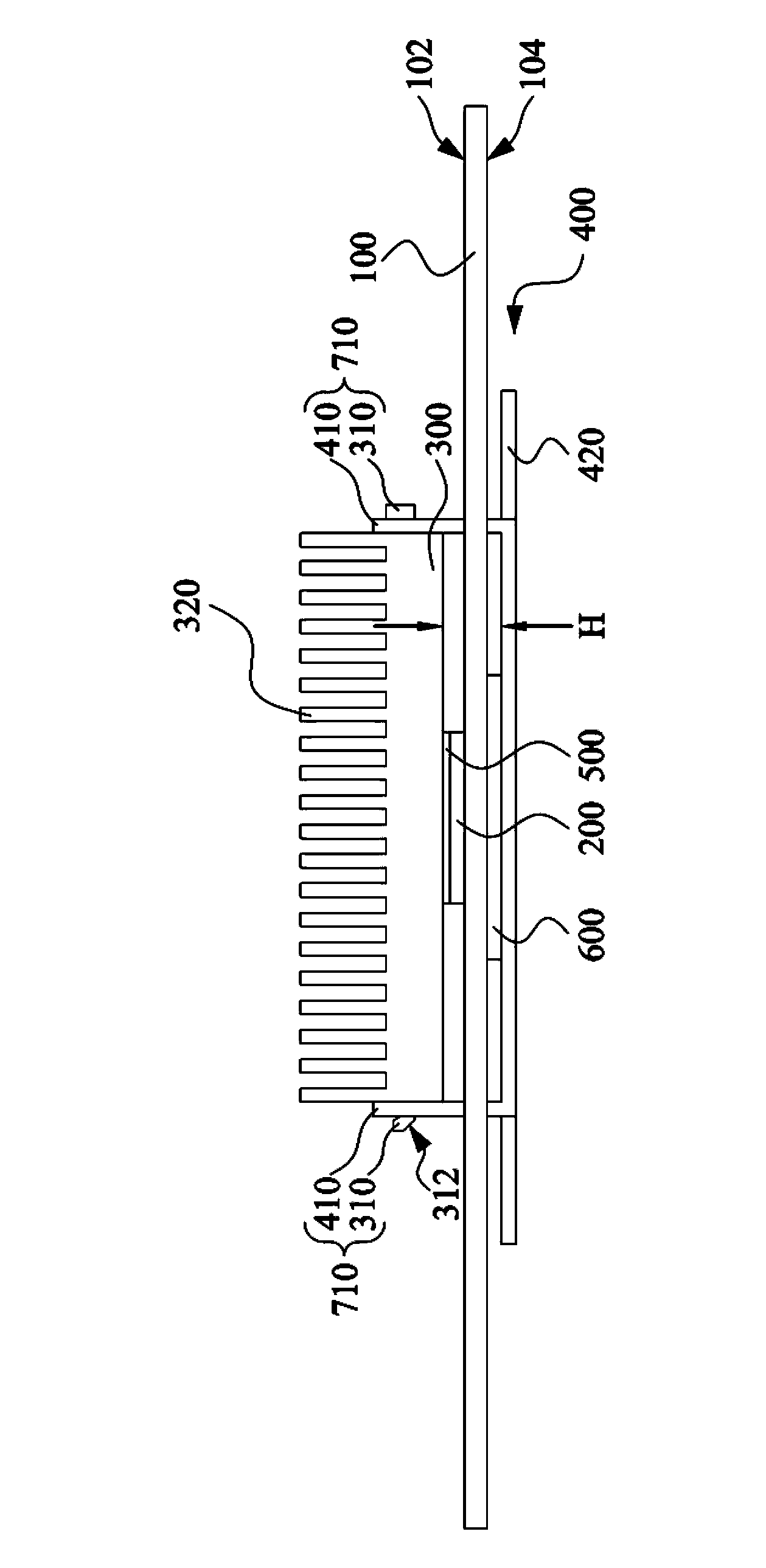
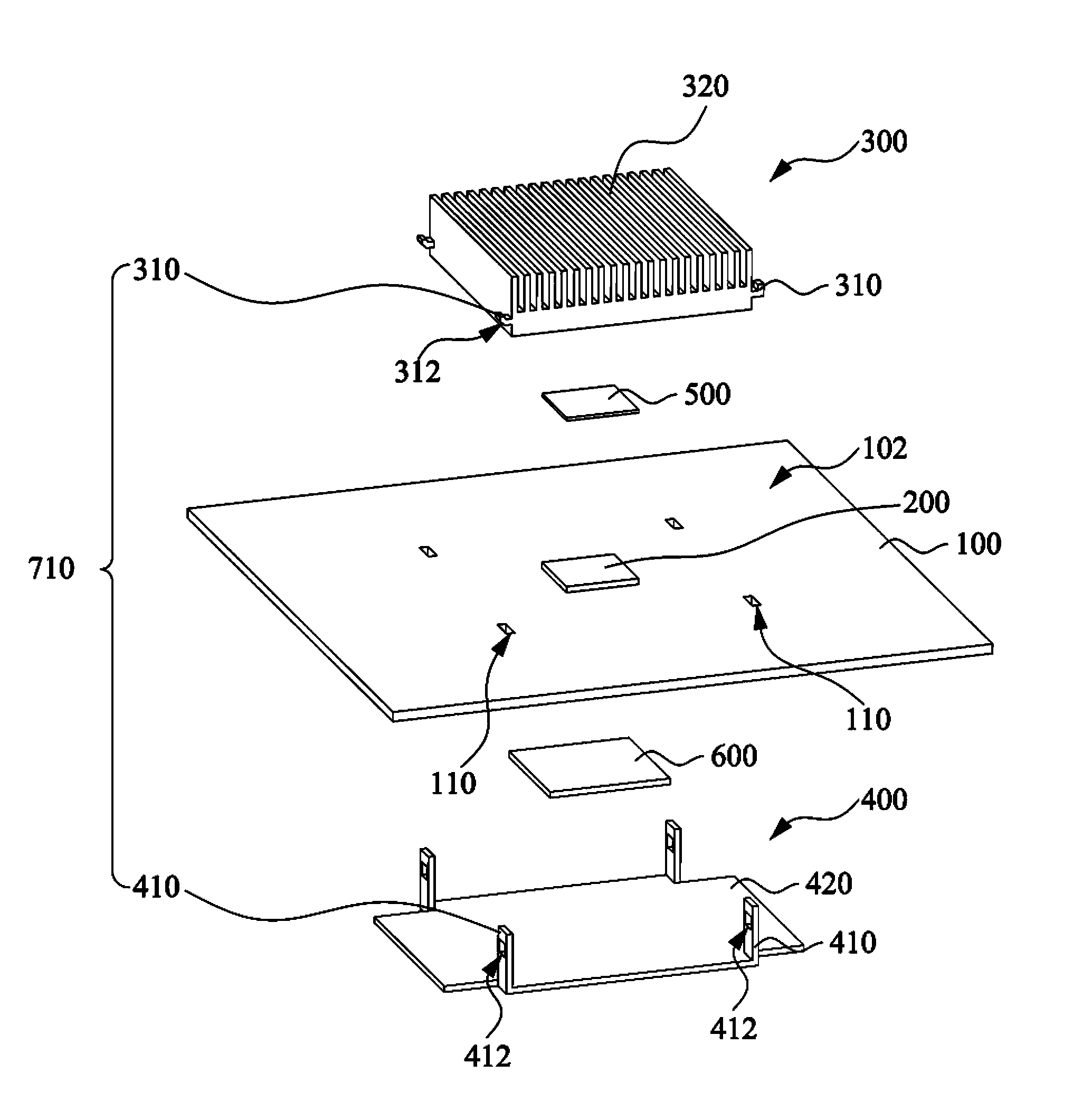
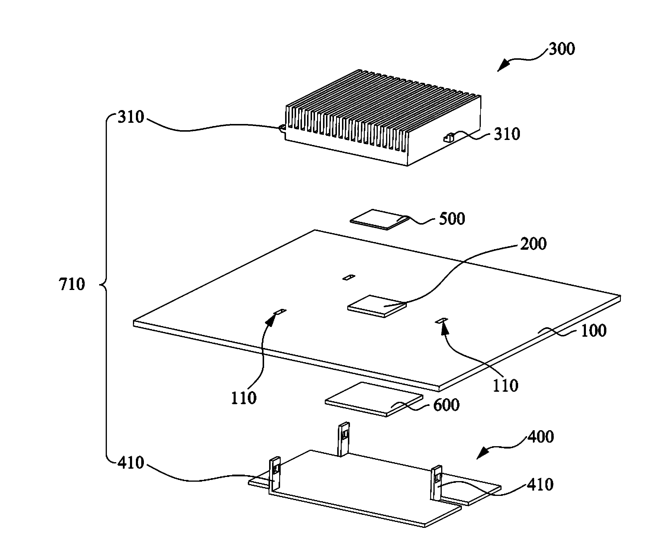
[0031] Please also refer to figure 1 and figure 2 ,in figure 1 A side view showing a heat dissipation assembly structure according to an embodiment of the present invention, figure 2 draw figure 1 An exploded view of the thermally assembled structure of . The heat dissipation assembly structure includes a circuit board 100 , a heat source 200 , a first heat dissipation element 300 , a second heat ...


PUM


Abstract

The invention discloses a heat dissipation assembly structure which comprises a circuit board, a heat source, a first heat dissipation element, a second heat dissipation element, a first heat dissipation medium and a second dissipation medium, wherein the circuit board is provided with a first main surface, a second main surface and a plurality of through holes, the first main surface and the second main surface are opposite to each other, the heat source is fixed on the first main surface of the circuit board, the first heat dissipation element is arranged on the first main surface of the circuit board and comprises a plurality of first engagement parts, the second heat dissipation element is arranged on the second main surface of the circuit board and comprises a plurality of a second engagement parts, one of each first engagement part and each second bucked part are mutually engaged to form an engagement structure, the engagement structures respectively pass through the through holes of the circuit board, the first heat dissipation medium is arranged between the first heat dissipation element and the heat source, and the second heat dissipation element is arranged between the second heat dissipation element and the circuit board.

Description

technical field [0001] The invention relates to a heat dissipation assembly structure. Background technique [0002] With the diversification of the functions of electronic products, the power consumption of the electronic components is also increasing day by day, and the temperature of the electronic components themselves is also increased accordingly. Since the performance of electronic components with high temperature will drop suddenly and may cause damage to the electronic components, the problem of heat dissipation has become an important issue. [0003] For electronic components with high power consumption, the heat dissipation structure generally needs to be more complicated to enhance the heat dissipation effect. However, the number of fixed components required by the complex heat dissipation structure also increases, which increases the cost of heat dissipation, and the complex heat dissipation structure may also cause uneven heat dissipation effects, resulting in...

Claims


Application Information

Patent Timeline
Patent Type & Authority Applications(China)
IPC IPC(8): H05K7/20
Inventor 蔡升宏陈馨恩刘湘肇
Owner WISTRON NEWEB
Why Eureka
Try Eureka