Heat exchanger and water heater

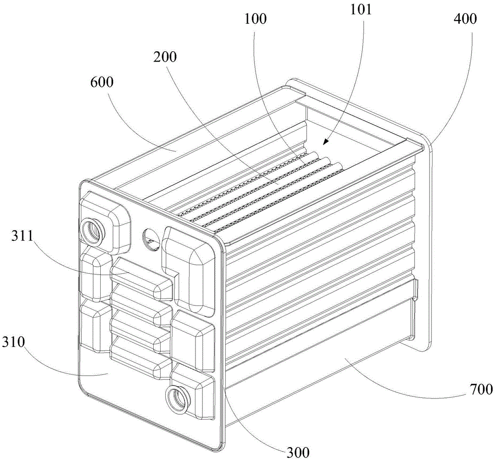
A heat exchanger and heat exchange tube technology, applied in the direction of heat exchanger types, indirect heat exchangers, lighting and heating equipment, etc., can solve the problem that the flue gas cannot be fully contacted with the heat exchange fins and the heat exchange Low efficiency, no diversion effect, etc., to achieve the effect of good heat exchange effect, improved heat exchange efficiency, and large heat exchange area

Active Publication Date: 2016-04-13
WUHU MIDEA KITCHEN & BATH APPLIANCES MFG CO LTD
View PDF8 Cites 11 Cited by
  • Summary
  • Abstract
  • Description
  • Claims
  • Application Information

AI Technical Summary

Problems solved by technology

[0002] At present, the heat exchanger used in the gas water heater industry performs heat exchange through heat exchange tubes and heat exchange fins. The heat exchange tubes pass through the heat exchange fins to form the heat exchange body. The method is mainly to interfere with the flue gas flow direction by pressurizing the thin plate or flanging holes. The heat exchange fins have no guiding effect on the flue gas flow in the direction of the flue gas flow, and cannot guide the flue gas to fully contact the heat exchange fins. , and the heat transfer area where the heat transfer fins are in contact with the flue gas is relatively small, so the heat transfer efficiency of the existing heat exchanger is low

Method used


Image

  • Heat exchanger and water heater
  • Heat exchanger and water heater
  • Heat exchanger and water heater

Examples


Embodiment Construction

[0048] The following will clearly and completely describe the technical solutions in the embodiments of the present invention with reference to the accompanying drawings in the embodiments of the present invention. Obviously, the described embodiments are only part of the embodiments of the present invention, not all of them. Based on the embodiments of the present invention, all other embodiments obtained by persons of ordinary skill in the art without creative efforts fall within the protection scope of the present invention.

[0049] It should be noted that all directional indications (such as up, down, left, right, front, back...) in the embodiments of the present invention are only used to explain the relationship between the components in a certain posture (as shown in the accompanying drawings). Relative positional relationship, movement conditions, etc., if the specific posture changes, the directional indication will also change accordingly.

[0050] In addition, the ...


PUM


Abstract

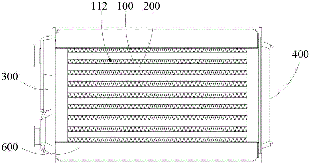
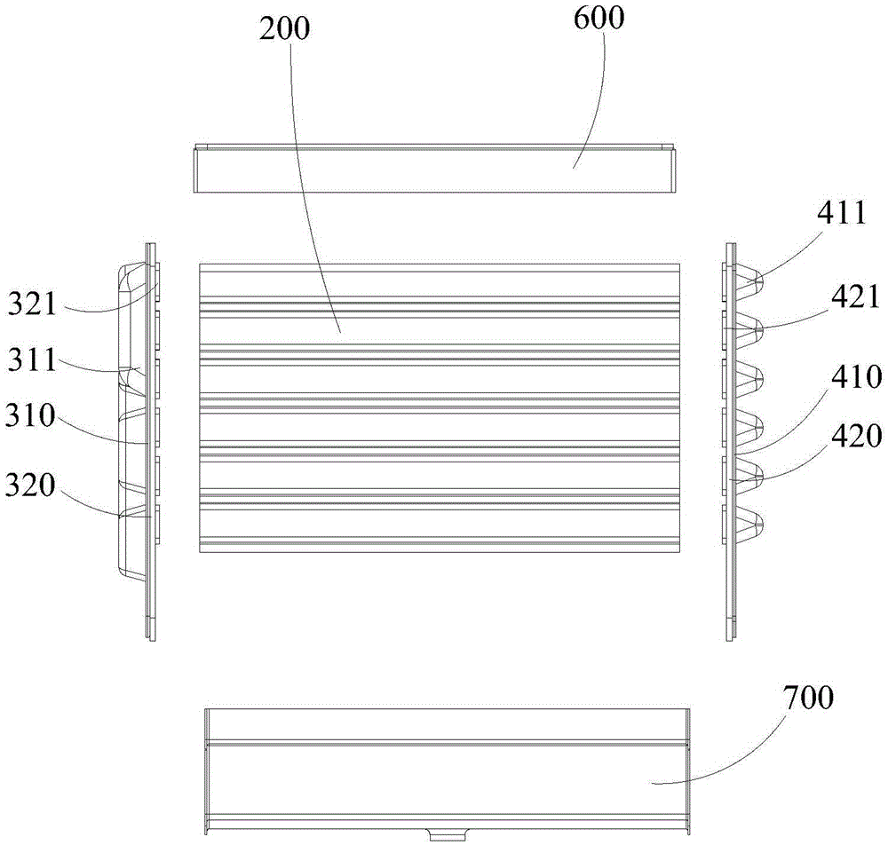
The invention discloses a heat exchanger and a water heater. The heat exchanger comprises heat exchange parts, a plurality of rows of heat exchange pipes, a first flow concentration end cover, and a second flow concentration end cover. An installation gap is formed between every two adjacent rows of heat exchange pipes. The heat exchange parts are arranged in the installation gaps, and each heat exchange part is arranged by attaching the corresponding two adjacent heat exchange pipes in the heat exchanger. The heat exchange parts comprise heat exchange pieces which are made of metal materials. The heat exchange pieces are bent back and forth in the thickness direction of the heat exchange pieces to form a wave shape, and therefore protrusions which are arranged at intervals are formed on the front faces and the back faces of the heat exchange pieces. A smoke passing way is formed between every two adjacent protrusions on the surface of the same side of each heat exchange piece, and smoke channels of the heat exchange pieces are composed of the smoke passing ways. The smoke channels of the heat exchange parts are communicated with a smoke inlet and a smoke outlet. The first flow concentration end cover and the second flow concentration end cover correspondingly cover the two ends of the multiple rows of heat exchange pipes, and the corresponding heat exchange pipes in the multiple rows of heat exchange pipes are communicated. According to the technical scheme, the heat exchange efficiency of the heat exchanger can be improved.

Description

technical field [0001] The invention relates to the technical field of water heaters, in particular to a heat exchanger and a water heater. Background technique [0002] At present, the heat exchanger used in the gas water heater industry performs heat exchange through heat exchange tubes and heat exchange fins. The heat exchange tubes pass through the heat exchange fins to form the heat exchange body. The method is mainly to interfere with the flue gas flow direction by pressurizing the thin plate or flanging holes. The heat exchange fins have no guiding effect on the flue gas flow in the direction of the flue gas flow, and cannot guide the flue gas to fully contact the heat exchange fins. , and the heat exchange area where the heat exchange fins contact the flue gas is relatively small, so the heat exchange efficiency of the existing heat exchanger is low. Contents of the invention [0003] The main purpose of the present invention is to provide a heat exchanger, aiming...

Claims


Application Information

Patent Timeline
Patent Type & Authority Applications(China)
IPC IPC(8): F28D7/16
CPCF28D7/16
Inventor 杜小文梁国荣黄官贤陆祖安
Owner WUHU MIDEA KITCHEN & BATH APPLIANCES MFG CO LTD
Why Eureka
Try Eureka