cleaning robot

A technology for cleaning robots and bodies, applied to machine parts, manual sweeping machines, vacuum cleaners, etc., can solve problems such as failure to successfully remove garbage particles, obstruction of garbage, and impact on cleaning efficiency

Active Publication Date: 2018-03-30
ECOVACS ROBOTICS (SUZHOU ) CO LTD
View PDF12 Cites 2 Cited by
  • Summary
  • Abstract
  • Description
  • Claims
  • Application Information

AI Technical Summary

Problems solved by technology

The disadvantage of this working method is that if the volume of the garbage particles exceeds the maximum volume that can pass through the gap between the roller brush and the ground, the garbage particles will not be successfully removed, thus reducing the cleaning efficiency; When it rotates, its shape is similar to a cylinder. When it moves forward, it will push some ground dust forward, which is not conducive to the ground dust being sucked into the ash suction channel.
Although this working method avoids the shortcomings of the roller brush cleaning backwards, but the rotating speed of the roller brush is relatively high and there is no cover on the front side of the suction port. The roller brush sweeps forward and it is easy to push away the garbage, especially the garbage with large particles. At the same time, the dust swept up by the roller brush is not easy to enter the suction port, which affects the further removal of dust
However, if a baffle is installed on the front side of the suction port, it will hinder the garbage from entering the suction port, which will also affect the cleaning efficiency.

Method used


Image

  • cleaning robot
  • cleaning robot
  • cleaning robot

Examples


Embodiment Construction

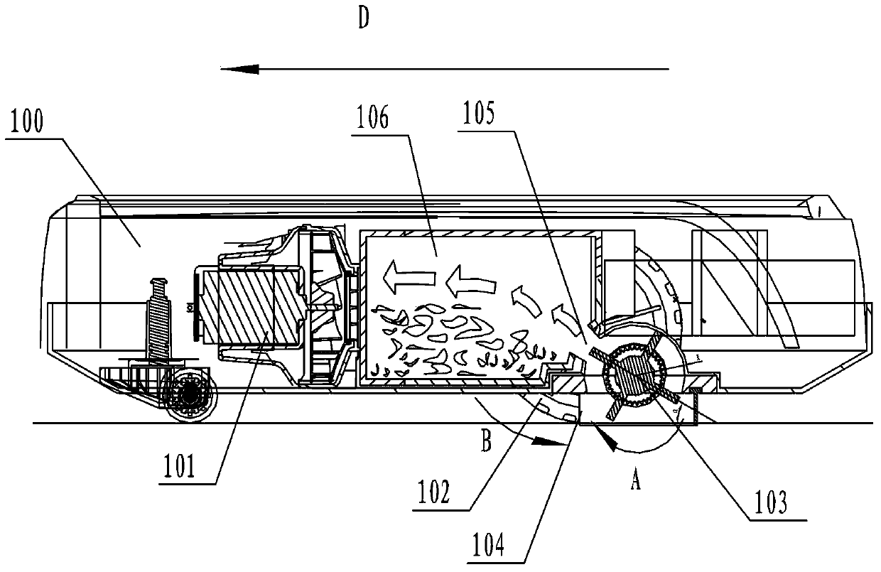
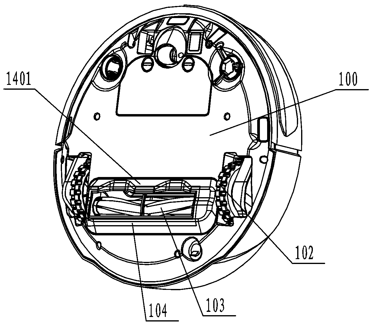
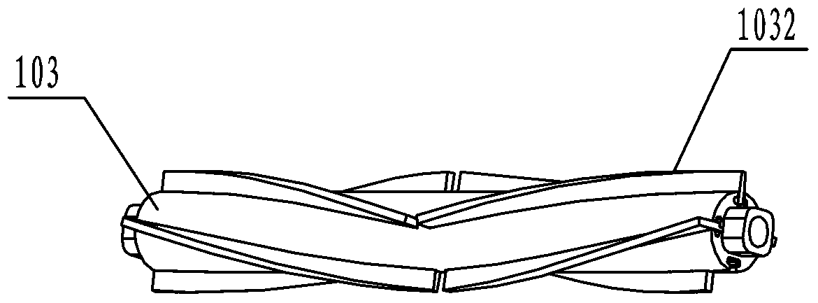
[0020] figure 1 It is a schematic cross-sectional view of the overall structure of the cleaning robot of the present invention; figure 2 It is a schematic diagram of the bottom structure of the cleaning robot of the present invention. Such as figure 1 and combine figure 2 As shown, the present invention provides a cleaning robot, including a body 100 and a dust collection chamber 106, a dust suction motor 101 and a dust collection channel 105 are arranged in the body, and a drive wheel 102, a rolling brush 103 and a suction wheel are arranged at the bottom of the body. Dust port 104 , the roller brush 103 is arranged at the dust suction port 104 . The dust is cleaned by the roller brush 103 , and is collected into the dust collection chamber 106 by the dust suction port 104 through the dust collection channel 105 under the suction effect of the dust collection motor 101 . Assuming that the moving direction of the cleaning robot during the cleaning operation is forward, t...


PUM


Abstract

A cleaning robot, the roller brush (103) is arranged at the dust suction port (104), the dust is cleaned by the roller brush, and is sucked by the dust suction motor (101) through the dust collection channel (105) Collected in the dust collection chamber (106); assuming that the direction of travel of the cleaning robot during the cleaning operation is the front, the rotation direction (A) of the roller brush is opposite to the rotation direction (B) of the driving wheel when the cleaning robot advances. The middle position of the front side of the dust suction port on the body extends from the shell to the surface to be cleaned to form a flange (1041); the roller brush is provided with spirally arranged bristles (1032), and as the roller brush rotates, the ends of the bristles The contact point with the surface to be cleaned moves from the end of the roller brush to the middle, so that the dust gathers towards the middle of the front side of the suction port. The size of the garbage particles to be cleaned in the present invention is not limited by the size of the gap between the roller brush body and the ground. The bristles on the roller brush are set in a "V"-shaped spiral structure, which cooperates with the flange structure on the front side of the dust suction port, and the cleaning efficiency is high. .

Description

technical field [0001] The invention relates to a vacuum cleaner, in particular to a cleaning robot used for cleaning floors, and belongs to the technical field of small household appliance manufacturing. Background technique [0002] During the working process, the cleaning robot usually does not need real-time control by the user. As it walks in the area to be cleaned, it can automatically absorb garbage including dust and debris to achieve automatic cleaning. Therefore, cleaning robots are more and more favored and widely used by consumers with their advantages of small size, flexible movement and automatic operation. [0003] The roller brush of the existing cleaning robot generally includes two working modes. If the moving direction of the cleaning robot is set as the front during cleaning operation, then the first working mode is: the rotating direction of the rolling brush and the rotating direction of the driving wheel when the cleaning robot advances. The same, tha...

Claims


Application Information

Patent Timeline
Patent Type & Authority Patents(China)
IPC IPC(8): A47L11/24A47L7/00A47L11/40
Inventor 沈象波
Owner ECOVACS ROBOTICS (SUZHOU ) CO LTD
Why Eureka
Try Eureka