Automatic mallet with damping device

A shock-absorbing device, electric hammer technology, applied in striking tools, manufacturing tools, lightweight impact tools, etc., can solve the problems of reducing the overall structural strength, misalignment of the hammer rod, and shortening the service life, so as to reduce the degree of distortion and deformation. , the effect of strengthening the structural strength and simplifying the overall structure

Active Publication Date: 2014-12-24
REXON IND CORP LTD
View PDF9 Cites 3 Cited by
  • Summary
  • Abstract
  • Description
  • Claims
  • Application Information

AI Technical Summary

Problems solved by technology

Although the use of the cantilever shrapnel can absorb the yaw shock during operation, this suspension design not only increases the overall volume of the housing, but also because the compression spring and the cantilever shrapnel will fully bear the operating force and reaction On the contrary, it will reduce the overall structural strength and has the disadvantage of poor durability
[0005] And another type of electric hammer damping device to improve the uneven stress on the handle, as disclosed in US Patent No. US7,523,791, is to pivot the handle at the rear of the body where the hammer rod and the drive group are installed, and use A shock-absorbing spring connected between the handle and the body provides yaw buffering, however, during operation of this type of design, the handle will swing around the pivot joint, so the shock-absorbing spring will simultaneously receive linear stress in the direction of movement of the hammer The force and the angle of the grip swinging pressure are stressed, and it is easy to distort and deform, resulting in problems such as reduced service life or inaccurate hitting points of the hammer rod.
[0006] US Patent No. 7,886,838 aims to improve the problem of twisting and deformation of a single shock-absorbing spring under pressure in different directions. Two groups of shock-absorbing springs are set, one of which is responsible for buffering the linear vibration caused by the action of the hammer rod, and the other It is responsible for buffering the yaw vibration caused by the swing of the grip. Although this design can slightly reduce the distortion problem of the single shock absorbing spring design, the use of multiple sets of shock absorbing mechanisms will make the overall structural design more complicated and thus increase the cost. Otherwise, the setting of multiple sets of damping springs will also increase the error range of the hammer rod hitting point, and there is still room for improvement

Method used


Image

  • Automatic mallet with damping device
  • Automatic mallet with damping device

Examples


Embodiment Construction

[0019] The present invention will be described in detail below in conjunction with the accompanying drawings and embodiments.

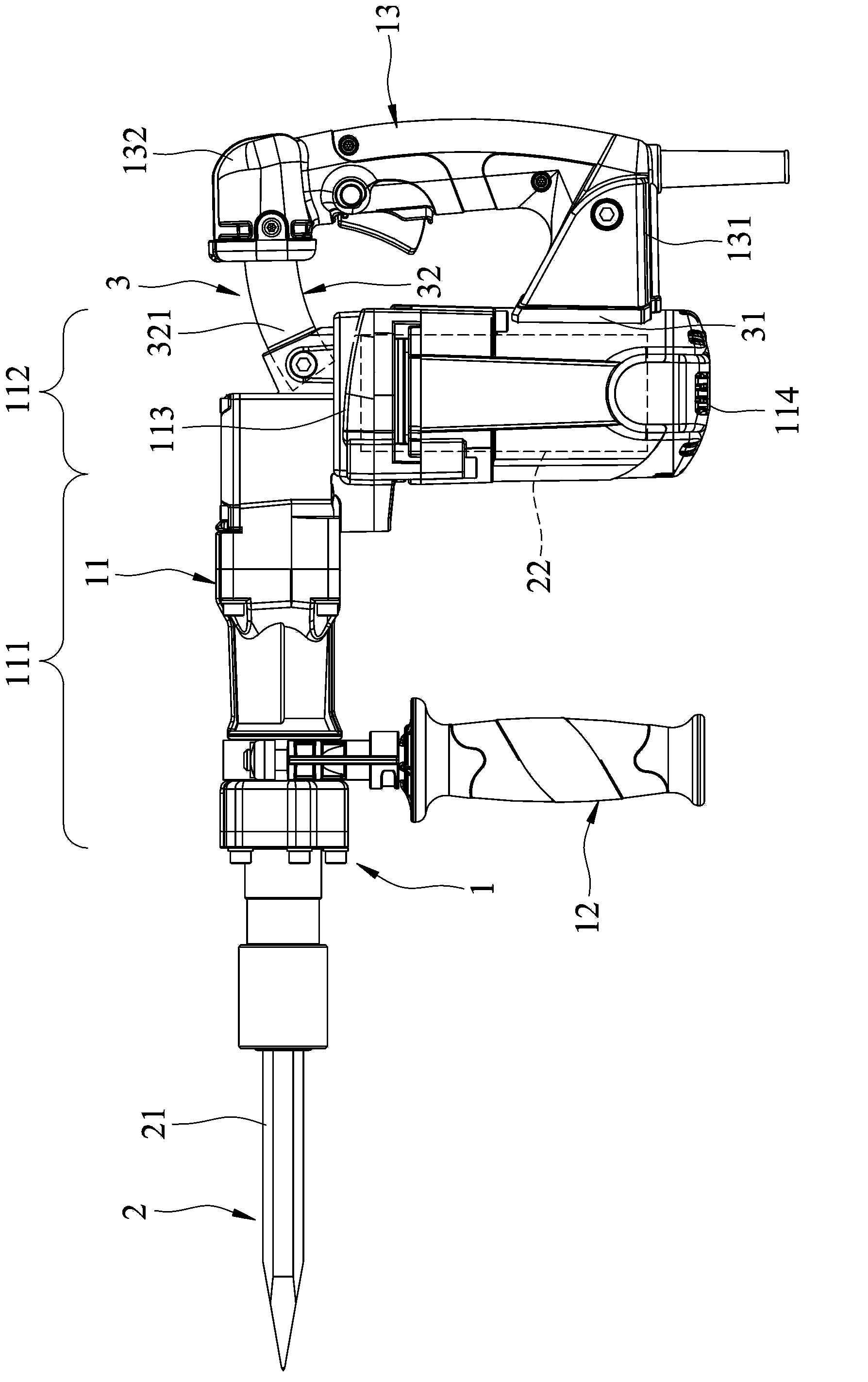
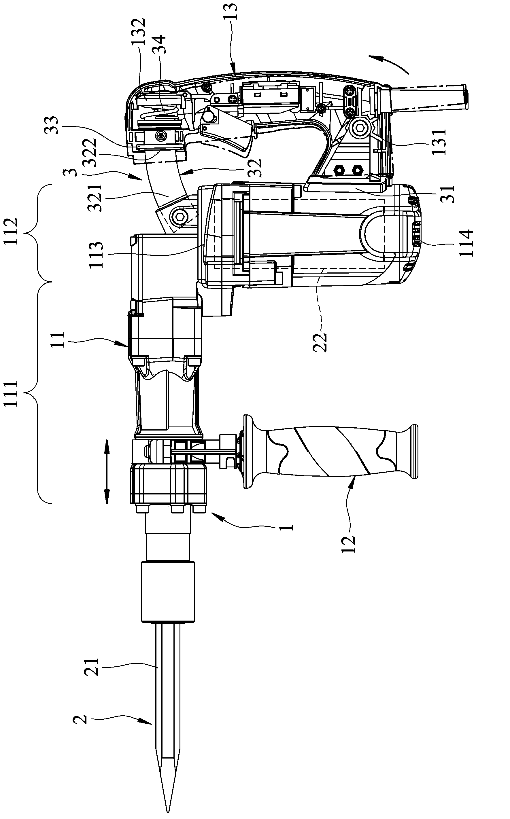
[0020] refer to figure 1 and figure 2 , a preferred embodiment of the electric hammer with a shock absorbing device in the present invention includes a housing unit 1 , an electric hammer unit 2 and a shock absorbing device 3 .

[0021] The housing unit 1 includes a housing 11 , an auxiliary handle 12 and a driving handle 13 .

[0022] The housing 11 is roughly L-shaped and has an opposite front end 111 and a rear end 112 , and the rear end 112 has an opposite upper side 113 and a lower side 114 connected to the front end 111 .

[0023] The auxiliary handle 12 is fixed below the front end 111 and parallel to the rear end 112 .

[0024] The driving handle 13 has a pivotal end 131 pivotally disposed on the rear end 112 , and a free end 132 opposite to the pivotal end 131 and capable of swinging with the pivotal end 131 as a fulcrum. . In this embo...


PUM


Abstract

Disclosed is an automatic mallet with a damping device. The automatic mallet comprises a shell unit, an automatic mallet unit and the damping device. The shell unit comprises a shell and a drive handle. The drive handle is provided with a pivot end, pivoted to the shell, and a free end. The free end can swing, with the pivot end used as the pivot. The automatic mallet unit comprises a mallet rod and a drive set. The mallet rod penetrates in the shell unit and is driven by the drive set to do reciprocating motion along the length thereof. The damping device comprises an orbit determined arc rod and an elastic member. The orbit determined arc rod is connected between the shell and the free end. The elastic member is abutted against between the orbit determined arc rod and the shell unit. The orbit determined arc rod extends along the swing path of the free end to movably penetrate the shell unit.

Description

technical field [0001] The invention relates to an electric hammer, in particular to an electric hammer with a shock absorbing device. Background technique [0002] A general electric hammer mostly has a roughly L-shaped body, a hammer shaft and a driving group respectively arranged on the body, and a handle mounted on the rear of the body. During use, the corresponding reaction force will be generated due to the reciprocating hammering of the hammer rod on the object to be struck, so that the operator often bears a large amount of vibration when holding the handle for operation. Once the operation time is prolonged, it is easy to Will cause hand joint injury, therefore, the grip shock absorption technology of many electric hammers appears. [0003] For example, the electric hammer damping device disclosed in US Patent No. US6,148,930 has an L-shaped body, a hammer rod and a driving group respectively arranged on the body, and a hollow U-shaped handle with an opening facing...

Claims


Application Information

Patent Timeline
Patent Type & Authority Applications(China)
IPC IPC(8): B25D11/00B25D17/24
Inventor 游文杰
Owner REXON IND CORP LTD
Why Eureka
Try Eureka