Staggered bevel for continuous compression molding tooling dies

A technology for processing molds and compression molding, which is applied to household appliances, other household appliances, applications, etc., and can solve problems such as hindering the sliding of laminated layers 5, increasing scrap rates and production costs, and reducing component quality

Active Publication Date: 2014-12-24
THE BOEING CO
View PDF6 Cites 0 Cited by
  • Summary
  • Abstract
  • Description
  • Claims
  • Application Information

AI Technical Summary

Problems solved by technology

This prevents the preformed laminate 5 from sliding well along the surfaces 3, 7 of the tooling tool 1 and can lead to the formation of wrinkles 10 in the foil and / or the preformed laminate 5
Wrinkling of these foils and / or preformed laminates 5 reduces part quality and increases scrap and production costs

Method used


Image

  • Staggered bevel for continuous compression molding tooling dies
  • Staggered bevel for continuous compression molding tooling dies
  • Staggered bevel for continuous compression molding tooling dies

Examples


Embodiment Construction

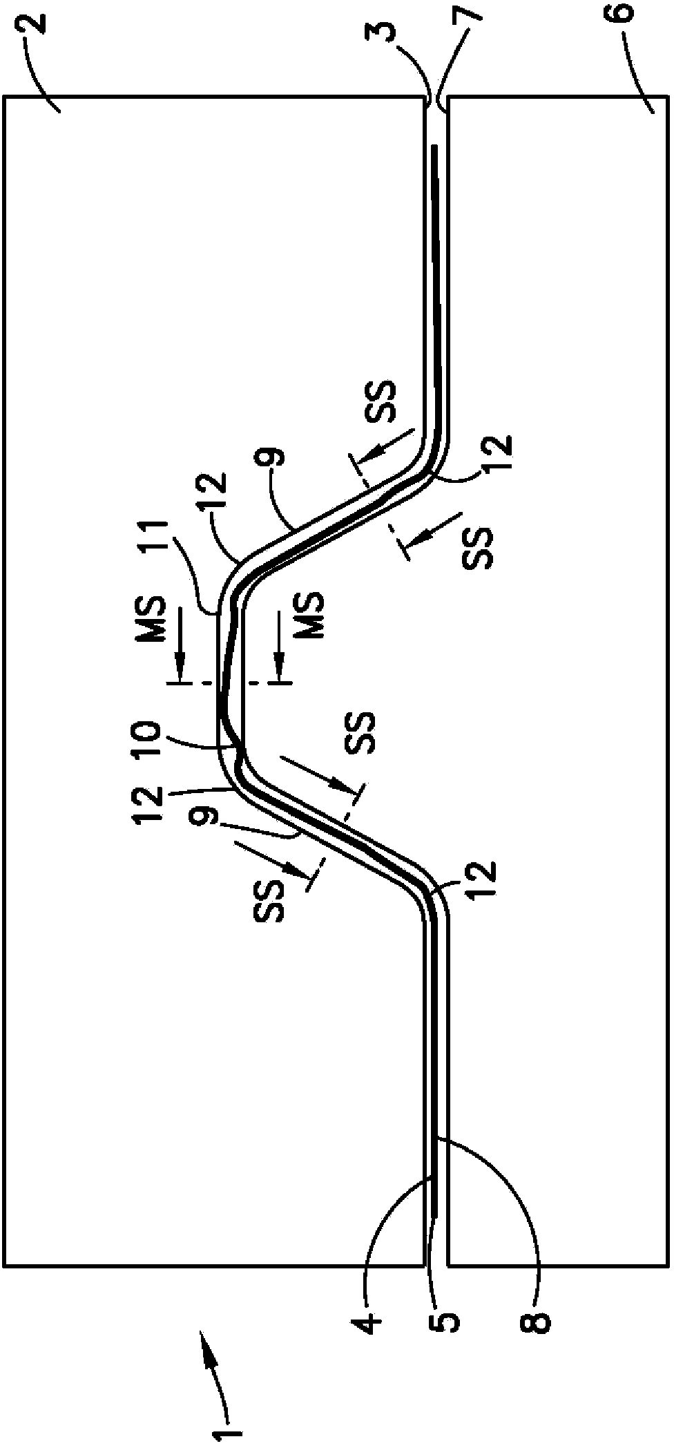
[0025] The following detailed disclosure describes a method and apparatus for continuous compression molding (CCM) of thermoplastic composite laminates with a tooling tool in the consolidation unit of a CCM process assembly having Nearby staggered bevel features. The staggered ramp feature allows excess material of the pre-formed stack to be pushed laterally outward from the middle of the tooling die towards the sides of the tooling die as it advances through the tooling die, and thus prevents Wrinkles form in thermoplastic composite parts.

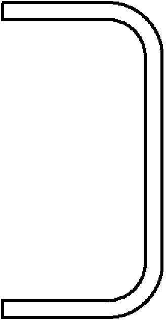
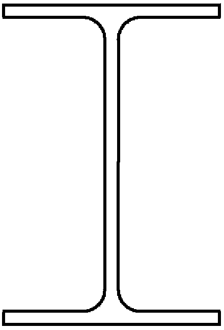
[0026] The disclosed method and apparatus can be used in the CCM process to fabricate thermoplastic composite parts having any cross-sectional configuration including, for example, flat or having one or more bends forming two or more segments Or the cross-sectional configuration of an arc segment, such as a "V"-shaped cross-sectional configuration. The staggered bevel feature of the method and apparatus provides reinforcement in fabrica...


PUM


Abstract

Continuous compression molded process and apparatus for fabricating thermoplastic composite parts from pre-formed thermoplastic composite laminates (5) with tooling dies (2,6) have a staggered bevel feature (44) at an entry side of the tooling dies (2,6). Staggering the length of the bevel feature (44) in each section between bends in a surface contour along the width of the incoming edge of the tooling dies (2,6) prevents excess material from being trapped and forming wrinkles in the finished thermoplastic part. The length of the taper (14,48) in each section along the width of the tooling dies (2,6) is aligned with a pulsed advancement distance of the pre-formed part (5).

Description

Background technique [0001] A large number of processes exist for making thermoplastic composite parts. In addition to discontinuous processes such as pressing, stamping and autoclaving, there are continuous processes such as extrusion, pultrusion, roll forming and compression molding. In commonly owned U.S. Patent Nos. 7,807,005 (Rubin et al.), 7,871,553 (Wilkerson et al.), and 8,333,858 (Rubin et al.), the use of thermoplastics for forming straight and curved, continuous lengths of varying cross-sectional configurations is shown. Examples of continuous fabrication processes for composite parts, each of which is hereby incorporated by reference in its entirety. [0002] The above process is suitable for a wide variety of potential applications including, for example, use in the aerospace industry. These processes are ideally suited for making thermoplastic composite parts, such as hardened components in the support frames of aircraft fuselages. Examples of thermoplastic co...

Claims


Application Information

Patent Timeline
IPC IPC(8): B29C70/54B29C70/34B29C33/00
CPCB29C33/00B29C70/34B29C70/54B29L2031/3076B29C70/46B29C70/526B29K2101/12B29B11/12B29C43/222B29C43/224B29C43/28B29C43/305B29C43/34B29C2033/422B29K2701/12B29C70/50
Inventor C·R·普雷柏尔R·D·威尔克尔松N·弗罗希纳
Owner THE BOEING CO
Why Eureka
Try Eureka