
Tube feeding device

A technology of feeding tubes and runners, which is applied in the direction of transportation and packaging, conveyor objects, rollers, etc. It can solve problems affecting the quality of steel tubes, collisions, time-consuming and labor-intensive problems, and achieve high-efficiency transmission

Inactive Publication Date: 2014-12-24
ZHANGJIAGANG CITY SHENGDINGYUAN PIPE MAKING
View PDF5 Cites 9 Cited by
  • Summary
  • Abstract
  • Description
  • Claims
  • Application Information

AI Technical Summary

Problems solved by technology

If the belt pulley is used for transmission, the steel pipes are prone to roll and collide with each other during transmission, which will affect the quality of the steel pipes; if the clamps are used for transmission, since the steel pipes need to be clamped, the operator needs to manually fix the steel pipes. Time-consuming and labor-intensive, the work efficiency is low, resulting in the delay of the entire steel pipe processing production line

Method used


Image

  • Tube feeding device
  • Tube feeding device
  • Tube feeding device

Examples


Embodiment Construction

[0020] The technical solutions provided by the present invention will be described in detail below in conjunction with specific examples. It should be understood that the following specific embodiments are only used to illustrate the present invention and are not intended to limit the scope of the present invention.

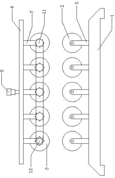
[0021] Such as figure 1 Shown is a schematic view of the structure of the present invention, the present invention is a tube feeding device, including a tube feeding bracket 1, a support runner 2, a tube feeding runner 3 and a pressing rod 4.

[0022] Two rows of support rods 5 are fixed vertically and uniformly along the pipe-inlet direction on the pipe-inlet bracket 1 .

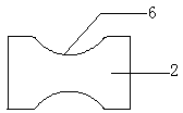
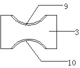
[0023] The two side end faces of the support runner 2 are connected with the support rod 5 in rotation, such as figure 2 As shown, the support runner 2 is provided with a circle of lower circular grooves 6; the lower circular grooves 6 are parallel to the direction of the pipe inlet, and its...


PUM


Abstract

The invention provides a tube feeding device, which comprises a tube feeding support, support turning wheels, tube feeding turning wheels and a compression rod; two rows of support rods are vertically, evenly and fixedly arranged along the tube feeding direction of the tube feeding support; both side end faces of each support turning wheel are rotatably connected with the corresponding support rod, and a circle of lower circular ring groove is formed in each support turning wheel; each lower circular ring groove is parallel with the tube feeding direction, and the cross section of each lower circular ring groove is cambered; two rows of tube feeding turning wheel connecting rods are downwards, vertically, evenly and fixedly arranged along the tube feeding direction of the compression rod, and the compression rod is also connected with a telescoping cylinder; both side end faces of each tube feeding turning wheel are rotatably connected with the corresponding tube feeding turning wheel connecting rod, and a circle of upper circular ring groove is formed in each tube feeding turning wheel; the cross section of each upper circular ring groove is cambered, and moreover, a circle of rubber ring wraps the cross section of each upper circular ring groove; the upper circular ring grooves are parallel with the tube feeding direction. According to the tube feeding device provided by the invention, steel tubes cannot transversally shift when being conveyed, and the phenomenon that damage caused by collision cannot occur; the steel tubes do not need to be clamped during steel tube conveyance; manual operation is not needed, and the steel tube conveying efficiency is high; the time and the labor are saved.

Description

technical field [0001] The invention belongs to the field of steel pipe processing equipment, and in particular relates to a pipe feeding device capable of efficiently transporting steel pipes. Background technique [0002] The processing of steel pipes includes multiple process steps. In order to make the processing of steel pipes more efficient, the equipment required to complete each process step is usually connected together, and steel pipe transmission connections are used in the middle to form a steel pipe processing production line. [0003] And existing steel pipe transmission device all is to transmit with belt pulley or use clamp to transmit. If the belt pulley is used for transmission, the steel pipes are prone to roll and collide with each other during transmission, which will affect the quality of the steel pipes; if the clamps are used for transmission, since the steel pipes need to be clamped, the operator needs to manually fix the steel pipes. Time-consu...

Claims


Application Information

Patent Timeline
Patent Type & Authority Applications(China)
IPC IPC(8): B65G13/02B65G13/07B65G39/02
Inventor 陈惠明
Owner ZHANGJIAGANG CITY SHENGDINGYUAN PIPE MAKING
Learn More