Water condenser, washing-drying machine and clothes drying method

A water condenser and condenser technology, applied in the field of washing and drying clothes, can solve the problems that the heat exchange plate is easily washed down by the water flow, the installation is cumbersome, and the structure is complicated, so as to improve the condensation efficiency, heat exchange efficiency, and drying efficiency. The effect of dry performance

Active Publication Date: 2014-12-24
QINGDAO HAIER WASHING MASCH CO LTD
View PDF5 Cites 20 Cited by
  • Summary
  • Abstract
  • Description
  • Claims
  • Application Information

AI Technical Summary

Problems solved by technology

By exchanging heat twice at the heat exchange plate and the air inlet of the condenser, the heat exchange efficiency of the washing machine is improved, the drying performance of the washing machine is improved, energy is saved, and high efficiency and energy saving are achieved. However, the inside of the condenser in the above patent The heat exchange plate is installed, the structure is complicated, the installation is cumbersome, and the heat exchange plate is easily washed off by the water flow

Method used


Image

  • Water condenser, washing-drying machine and clothes drying method
  • Water condenser, washing-drying machine and clothes drying method
  • Water condenser, washing-drying machine and clothes drying method

Examples


Embodiment 1

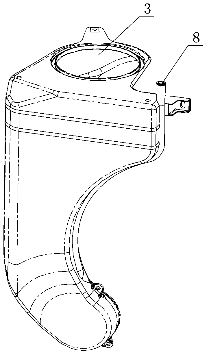
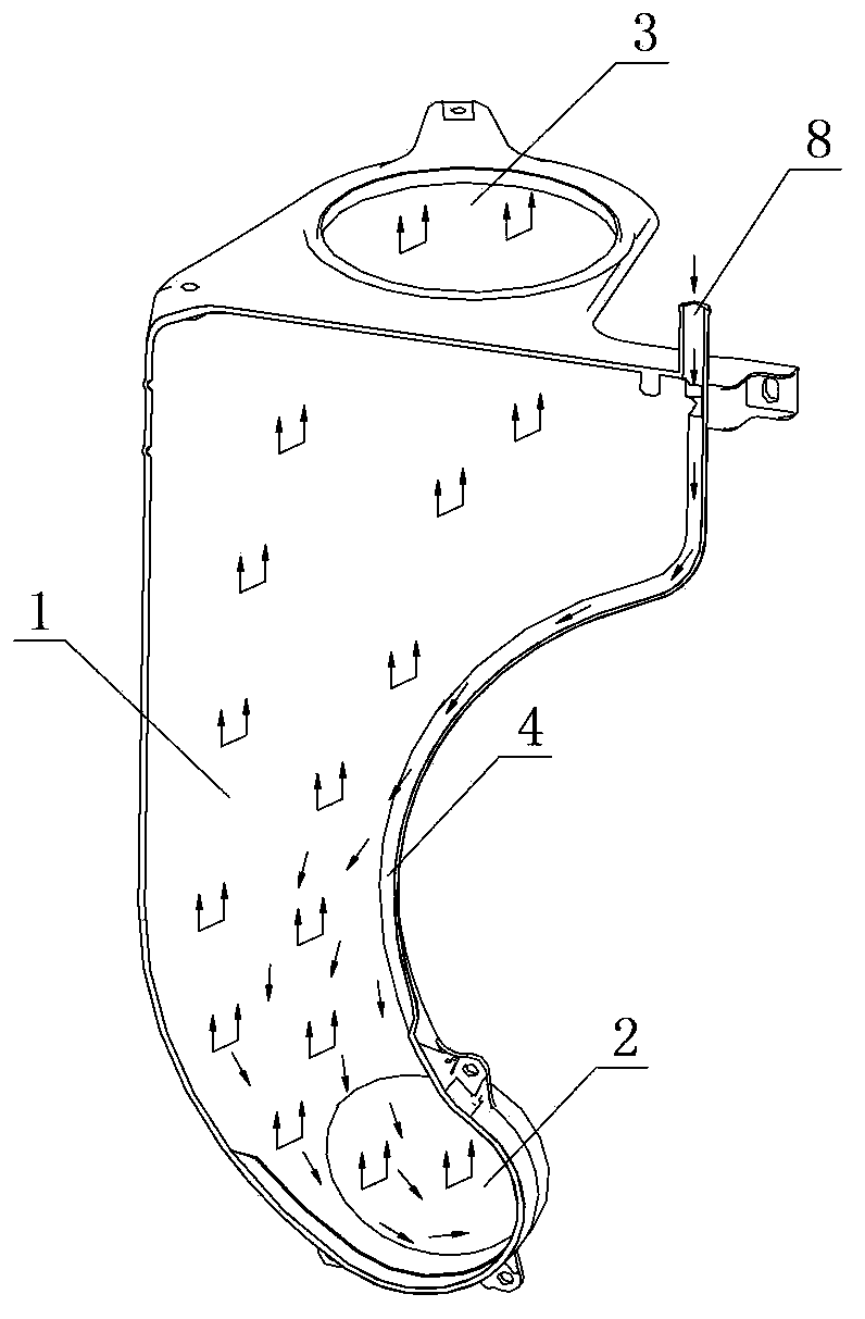
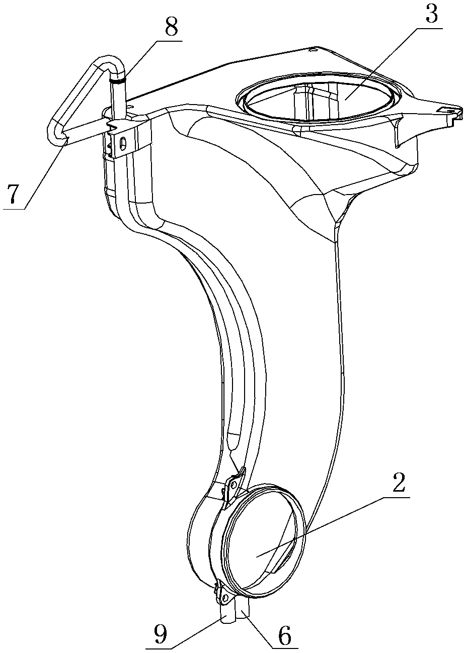
[0043] Such as image 3 , Figure 4 , Figure 5 As shown, the water condenser in this embodiment includes a condenser chamber 1, a hot and humid air inlet 2 located at the lower part of the condenser chamber 1, a dry air outlet 3 located at the upper part of the condenser chamber 1, and a The direct heat exchange condensate flow channel 4 on the inner wall and the indirect heat exchange condensate water interlayer 5 located on the outer wall of the condenser chamber 1, the condensate water in the condensate water flow channel 4 directly contacts the hot and humid air in the condenser chamber 1 for heat exchange , the condensed water in the condensed water interlayer 5 exchanges heat indirectly with the hot and humid air through the chamber wall of the condenser.

[0044] The lower part of the condensed water interlayer 5 is provided with the first condensed water inlet 6, the upper part of the condensed water interlayer 5 is provided with the first condensed water outlet 7, ...

Embodiment 2

[0048] Such as Figure 6 As shown, the water condenser in this embodiment includes a condenser chamber 1, a hot and humid air inlet 2 located at the lower part of the condenser chamber 1, a dry air outlet 3 located at the upper part of the condenser chamber 1, and a The direct heat exchange condensate flow channel 4 on the inner wall and the indirect heat exchange condensate water interlayer 5 located on the outer wall of the condenser chamber 1, the condensate water in the condensate water flow channel 4 directly contacts the hot and humid air in the condenser chamber 1 for heat exchange , the condensed water in the condensed water interlayer 5 exchanges heat indirectly with the hot and humid air through the wall of the condenser chamber 1 .

[0049] The lower part of the condensed water interlayer 5 is provided with the first condensed water inlet 6, the upper part of the condensed water interlayer 5 is provided with the first condensed water outlet 7, the upper part of the ...


PUM


Abstract

The invention relates to a water condenser, a washing-drying machine and a clothes drying method. The water condenser comprises a condenser chamber, a hot and humid air inlet, a dry air outlet, a condensed water flow path and a condensed water interlayer. The hot and humid air inlet is formed in the lower portion of the condenser chamber. The dry air outlet is formed in the upper portion of the condenser chamber. The condensed water flow path is formed on the inner wall of the condenser chamber and used for direct heat exchange. The condensed water interlayer is arranged on the outer wall of the condenser chamber and used for indirect heat exchange. The hot and humid air inlet of the water condenser is communicated with a roller of the washing-drying machine. After communicated with an air exhausting device of the washing-drying machine, the dry air outlet of the water condenser is further communicated with the roller through a heating device, thus a cycling air path is formed to dry the clothes. During drying, the direct heat exchange and the indirect heat exchange between the condensed water and the hot and humid air occur simultaneously, in this way, condensation efficiency is improved, heat exchange efficiency is further increased, drying performance is promoted, the condensed water is recycled, secondary heat exchange is realized, the condensed water is saved during clothes drying, energy is greatly saved, and high efficiency and energy conservation are achieved.

Description

technical field [0001] The invention relates to the field of washing and drying, in particular to a water condenser, an integrated washing and drying machine with the water condenser, and a clothes drying method of the integrated washing and drying machine. Background technique [0002] The drying device in the existing all-in-one washing and drying machine includes: an air supply device, a heating device, a condenser, and a water supply device. One side of the condenser is connected with the drum, and the other side is connected with the air supply device. When drying clothes, the air heated by the heating device (heating pipe) enters the drum driven by the fan, so that the clothes in the drum undergo heat exchange, the water evaporates, and the hot and humid air enters the condenser from bottom to top, and the water supply device The condensed water provided flows from top to bottom, and the two generate heat exchange in the condenser. The moisture in the hot and humid ai...

Claims


Application Information

Patent Timeline
Patent Type & Authority Applications(China)
IPC IPC(8): D06F58/24D06F58/28
CPCD06F58/24D06F58/30D06F58/38D06F2103/08
Inventor 许升宋华诚徐永洪单世强田书君
Owner QINGDAO HAIER WASHING MASCH CO LTD
Why Eureka
Try Eureka