
A post-grouting device for prefabricated piles and its technology

A technology of prefabricated piles and post-grouting, which is applied in the direction of sheet pile walls, foundation structure engineering, construction, etc., can solve the problems of prolonging the pile sinking period, affecting the friction resistance of the pile body, and being difficult to promote, so as to improve the quality of pile sinking and improve Stress condition and the effect of improving pile sinking efficiency

Inactive Publication Date: 2016-09-14
顾孙平
View PDF6 Cites 0 Cited by
  • Summary
  • Abstract
  • Description
  • Claims
  • Application Information

AI Technical Summary

Problems solved by technology

The first one is the "sinking method of synchronous grouting static pressure prefabricated piles". To meet the needs of all piles, the increase in the side resistance of prefabricated piles is very limited, and it increases the complexity of the pile sinking process and prolongs the pile sinking cycle. After the pile sinking is completed, the grouting cannot solve the gap at the pile end caused by soil extrusion problem, especially with pile groups, and the pile sinking method is limited to static piles
The second is "post-grouting prestressed pipe pile at the bottom of the pile". This method is a new type of pipe pile with a grouting device, but it is not suitable for all prefabricated piles, and it cannot solve the problem of the soft soil below the bearing layer. The reinforcement of this kind of pile cannot achieve the purpose of overall control of settlement. This kind of pile is difficult to manufacture and popularize.
The third type is "Prestressed Concrete Pipe Pile Enlarged Head Rear Grouting Device", which is a grouting device for the enlarged head of the pipe pile. The disadvantage is that the pipe pile with the enlarged head will affect the frictional resistance of the pile body. , and increase the difficulty of pile sinking

Method used


Image

  • A post-grouting device for prefabricated piles and its technology
  • A post-grouting device for prefabricated piles and its technology
  • A post-grouting device for prefabricated piles and its technology

Examples


Embodiment 1

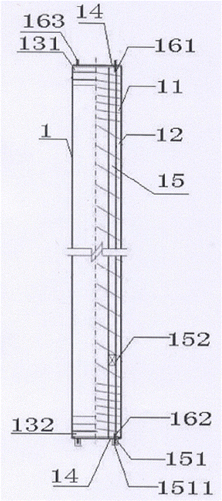
[0039] Embodiment 1: the prefabricated pile that adopts is pipe pile, as Figure 6 As shown, the bolt hole I 1321 and the bolt hole II 1322 on the end plate 132 below are the grouting holes 14, so that the grouting holes 14 are all on the same circumference, have the same hole diameter, and are symmetrically arranged to ensure that the pipe pile 1 maintains balance during the centrifugation process. Eccentric vibration does not occur. Such as Figure 7 As shown, two grouting pipes 15 are provided. The grouting pipes 15 are galvanized pipes with an inner diameter of Ф15 mm. The grouting device 151 is also provided with a protection device 1511. holes to facilitate the outflow of grout. The protection device 1511 is wrapped on the outside of the grouting device 151 and welded to the end of the grouting device 151. At the same time, the protection device 1511 is welded and fixed on the lower end plate 132 to prevent the grouting device 151 from being in the pile sinking process....

Embodiment 2

[0040] Embodiment 2: the prefabricated pile that adopts is pipe pile, as Figure 10 As shown, in the middle of bolt hole I 1321 and bolt hole III 1323, in the middle of bolt hole II 1322 and bolt hole IV 1324, two grouting holes 14 are arranged symmetrically, and according to these two grouting holes 14, as Figure 11 As shown, two grouting pipes 15 are provided, and the grouting pipes 15 are galvanized pipes with an inner diameter of Ф15 mm. The grouting device 151 is also provided with a protection device 1511, and the protection device 1511 is provided with through holes on both side plates to facilitate the outflow of the slurry.

Embodiment 3

[0041] Embodiment 3: the prefabricated pile 1 that adopts is a hollow pipe pile, such as Figure 12 As shown, two grouting pipes 15 are arranged in the hollow of the prefabricated pile 1, and the lower end of the grouting pipe 15 is welded to the lower end plate 132. In order to withstand the resistance of the end soil, the connection part is strengthened, and a protective device 1511 is provided. The protection device 1511 is provided with through holes on both side plates to facilitate the outflow of slurry. The grouting pipe 15, the lower end plate 132 and the protection device 1511 are welded to each other. The diameter of the grouting pipe is usually a galvanized steel pipe with an inner diameter of Ф25mm as the grouting pipe. When the prefabricated piles have spud cans 6, this embodiment only takes the spud cans as an example, and other types of spud cans are implemented by reference. The spud cans 6 are fixed at the lower end plate 132, such as Figure 13 , Figure 1...


PUM


Abstract

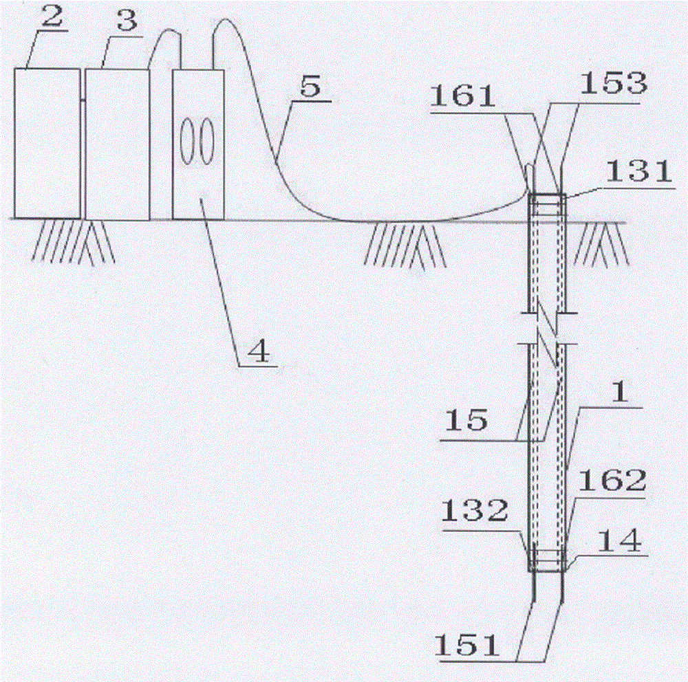
The invention relates to the technical field of foundation stabilization, in particular to a precast pile post-grouting device and a precast pile post-grouting process. The technical scheme adopted by the invention is that the precast pile post-grouting device comprises a precast pile, a stirrer, a slurry tank, a grouting pump and a grouting hose; a pile body of the precast pile is provided with a prestressed reinforcement, a spiral bar, an upper end plate and a lower end plate. The precast pile post-grouting device is characterized in that grouting holes are also formed in the precast pile, and the precast pile is also provided with grouting pipes, an upper transition pipe and a lower transition plate. Compared with the prior art, the precast pile post-grouting device and the precast pile post-grouting process have the beneficial effects that a construction process of pile tip and pile tip peripheral grouting and the arrangement form of the grouting pipes can be realized on piles with various pile diameters (large diameters and small diameters), various pile types (square piles, round piles, hollow piles and solid piles) and various pile lengths (short piles and long piles), and the problems of a post-grouting construction method of all precast pile types are solved.

Description

technical field [0001] The invention relates to the technical field of foundation reinforcement, in particular to a prefabricated pile post-grouting device and a process thereof. Background technique [0002] Prefabricated piles are building foundation components made in factories or construction sites. They are composed of various materials and forms, such as wooden piles, concrete square piles, prestressed concrete pipe piles, prestressed concrete hollow square piles, steel piles, etc. Pile driving equipment is usually used to drive, press or vibrate the piles into the soil. In civil engineering construction, prefabricated piles are mainly used in two categories: concrete prefabricated piles and steel piles. Concrete prefabricated piles can withstand large loads, are durable and fast in construction. They are one of the widely used pile types, but their construction has a great impact on the surrounding environment. Commonly used concrete solid square piles and prestresse...

Claims


Application Information

Patent Timeline
Patent Type & Authority Patents(China)
IPC IPC(8): E02D15/04E02D5/50
Inventor 顾孙平
Owner 顾孙平
Learn More