Miniature pneumatic power device

A pneumatic power, miniature technology, applied in the direction of machines/engines, liquid displacement machines, pumps with flexible working elements, etc., can solve problems such as loud noise, inability to achieve portability, difficulty in thinning, etc.

Active Publication Date: 2014-12-24
MICROJET TECH
View PDF5 Cites 76 Cited by
  • Summary
  • Abstract
  • Description
  • Claims
  • Application Information

AI Technical Summary

Problems solved by technology

[0005] The object of the present invention is to provide a kind of micro pneumatic power device suitable for portable or wearable instrument or equipment, by integrating micro gas transmission device and micro valve d

Method used


Image

  • Miniature pneumatic power device
  • Miniature pneumatic power device
  • Miniature pneumatic power device

Examples


Embodiment Construction

[0079] Some typical embodiments embodying the features and advantages of the present invention will be described in detail in the description in the following paragraphs. It should be understood that the invention is capable of various changes in different aspects without departing from the scope of the invention, and that the description and illustrations therein are illustrative in nature and not limiting. this invention.

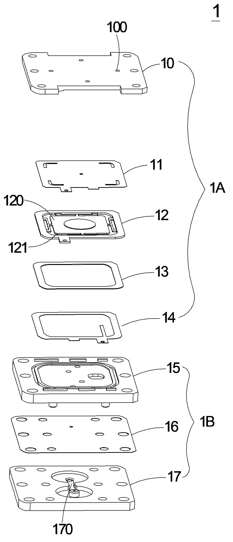
[0080] The micro-pneumatic power device 1 of the present invention can be applied to industries such as medical biotechnology, energy, computer technology, or printing to transmit gas, but is not limited thereto. see figure 1 , which is a schematic diagram of the front exploded structure of the micro pneumatic power device in the first preferred embodiment of the present invention. As shown in the figure, the micro pneumatic power device 1 of the present invention is composed of a micro gas transmission device 1A and a micro valve device 1B, wherein the...


PUM


Abstract

The invention discloses a miniature pneumatic power device which comprises a miniature air transmission unit. The miniature air transmission unit comprises an air intake plate, a runner plate, a resonance piece and a piezoelectric actuator which are arranged by stacking, a gap reserved between the resonance piece and the piezoelectric actor forms a first chamber, and when the piezoelectric actuator is driven, air is led into the first chamber from the air intake plate via the runner plate and the resonance piece and then transmitted downwards, and a pressure gradient runner is formed to have the air continuously pushed out; a miniature valve unit comprises an air collecting plate, a valve slice and an outlet plate which are arranged by stacking; when downwardly transmitted to an air collecting chamber from the miniature air transmission unit, the air is then transmitted to the interior of the miniature valve unit, so that a valve hole of the valve slice is enabled to be opened or closed due to one-way flow of the air to perform pressure collecting or pressure releasing.

Description

technical field [0001] The invention relates to a pneumatic power device, in particular to a miniature ultra-thin and quiet micro pneumatic power device. Background technique [0002] At present, in various fields, whether it is medicine, computer technology, printing, energy and other industries, products are developing towards refinement and miniaturization. Among them, micro pumps, sprayers, inkjet heads, industrial printing devices and other products include products. The fluid conveying structure is its key technology, so how to break through its technical bottleneck with an innovative structure is an important content of development. [0003] For example, in the pharmaceutical industry, many instruments or equipment that need to be driven by pneumatic power usually use traditional motors and pneumatic valves to achieve the purpose of gas delivery. However, limited by the volume limitations of the traditional motors and gas valves, it is difficult to reduce the volume ...

Claims


Application Information

Patent Timeline
IPC IPC(8): F04B45/047
Inventor 薛达伟张英伦吴祥涤余荣侯陈世昌周宗柏李耀吉廖家淯
Owner MICROJET TECH
Why Eureka
Try Eureka