Vehivle disc brake

A technology for disc brakes and vehicles, which is applied in the direction of brake types, brake components, axial brakes, etc., and can solve problems such as troublesome riveting operations

Inactive Publication Date: 2014-12-24
NISSIN KOGYO CO LTD
View PDF10 Cites 18 Cited by
  • Summary
  • Abstract
  • Description
  • Claims
  • Application Information

AI Technical Summary

Problems solved by technology

Therefore, the riveti

Method used


Image

  • Vehivle disc brake
  • Vehivle disc brake
  • Vehivle disc brake

Examples


Embodiment Construction

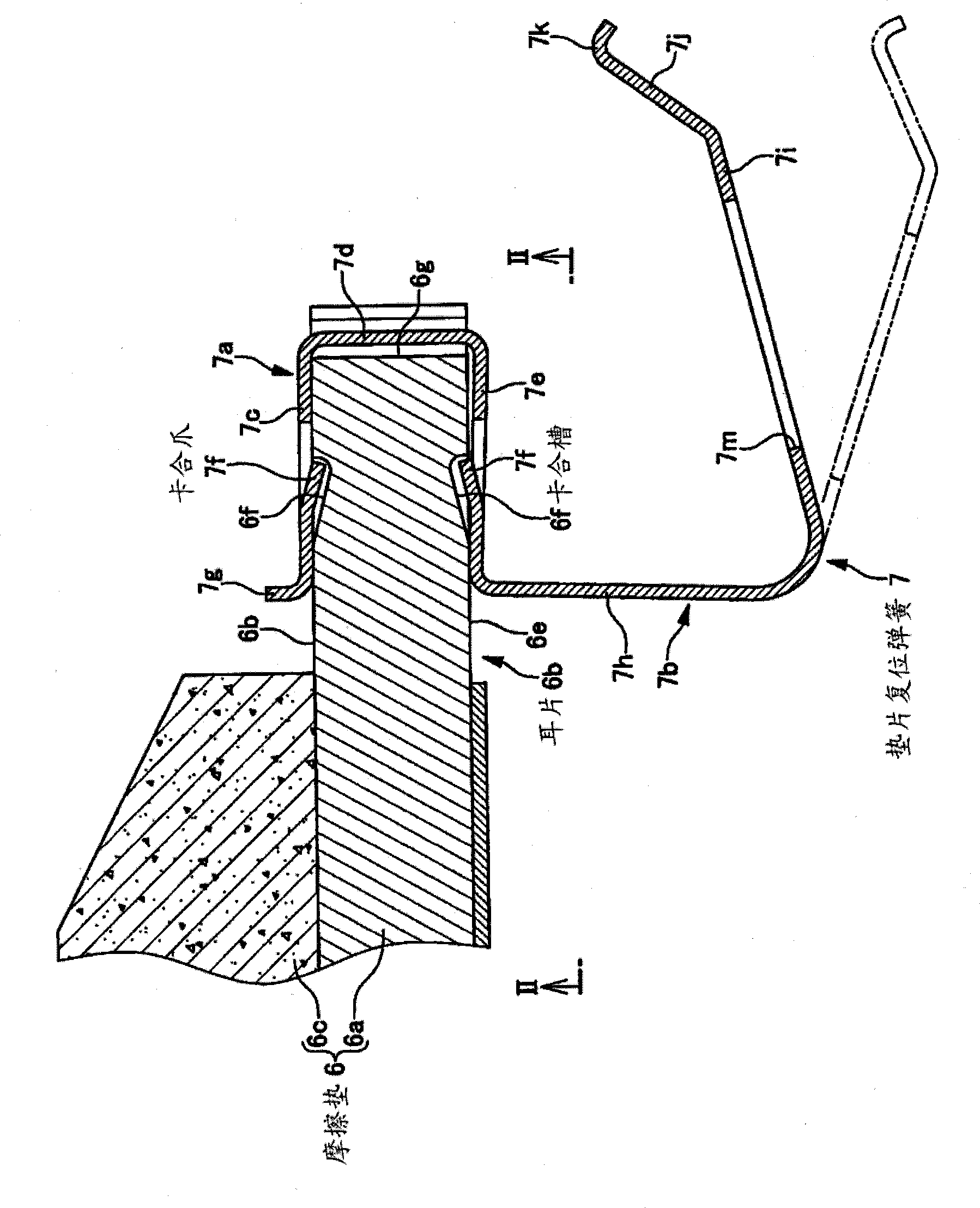
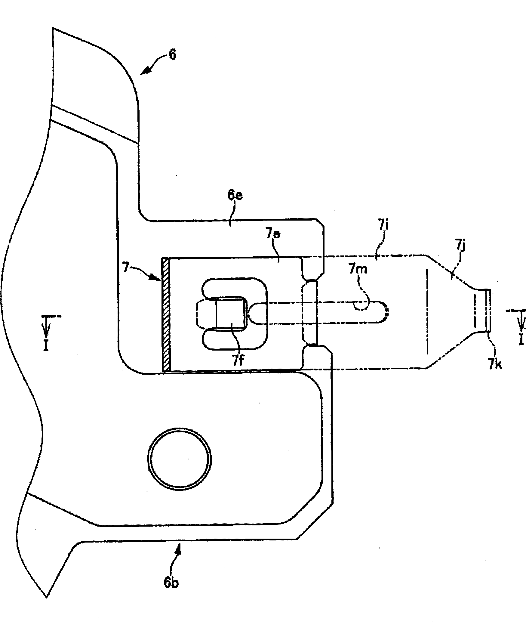
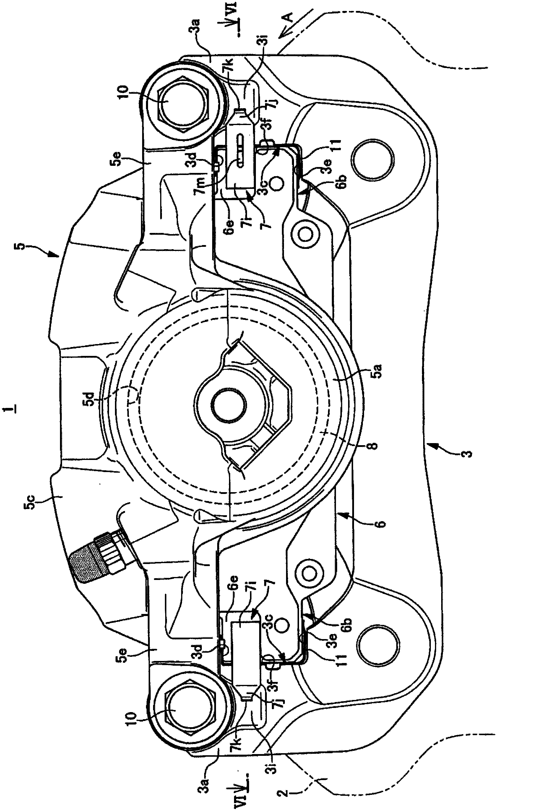
[0073] Figure 1~Figure 9 This shows a disc brake for a vehicle according to an embodiment. The arrow mark A is the direction of rotation of the disc rotor that rotates integrally with the front wheels when the vehicle moves forward. In the following, "disk turning-out side" and "disk turning-in side" refer to the disk turning-out side and disk turning-in side when the vehicle is moving forward.

[0074] The disc brake 1 for a vehicle includes a disc rotor 2, a caliper holder 3, a caliper body 5, a pair of friction pads 6 and 6, and four pad return springs 7. The disc rotor 2 rotates integrally with the wheel. The caliper bracket 3 is fixed to the vehicle body on one side of the disc rotor 2. The caliper body 5 is supported by the caliper support arms 3a, 3a of the caliper holder 3 via a pair of sliding pins 4, 4 so as to be movable in the axial direction of the disc. A pair of friction pads 6 and 6 are arranged inside the action portion 5a and the reaction portion 5b of the ...


PUM


Abstract

Provided is a vehivle disc brake. Each pad return spring (7) includes a lug piece attachment portion (7a) that is attached to a corresponding lug piece (6b), and a pad return portion (7b). The lug piece attachment portion (7a) of each pad return spring (7) includes a first piece that is disposed on a first surface, on a disc rotor side, of the corresponding lug piece, a second piece (7e) that is disposed on a second surface (6e), on the opposite side to the disc rotor side, of the corresponding lug piece, and a connection piece that connects the first piece and the second piece (7e). The lug piece attachment portion (7a) of each pad return spring (7) has a substantially U shape in section. The lug piece attachment portions (7a) are formed with engagement claw portions (7f), and the lug pieces (6b) are formed with engagement grooves (6f).

Description

Technical field [0001] The present invention relates to a disc brake for a vehicle used in vehicles such as automobiles and two-wheeled vehicles, and more particularly to a vehicle equipped with a shim return spring for forcibly separating a friction pad from a disk rotor when the brake is released Disc brakes. Background technique [0002] Disc brakes for vehicles include a caliper holder, a pair of friction pads, and a shim return spring. The brake caliper bracket is fixed to the body. In addition, the caliper holder has a caliper support wrist. A pair of friction pads sandwich the disc rotor and are arranged. Each friction pad has a back plate having a side portion. The shim return springs are arranged between the side of the back plate and the caliper support arm. When the brake is released, the shim return spring urges the friction pad to the opposite side of the disc rotor. Each shim return spring is arranged between the side of the back plate and the caliper support ...

Claims


Application Information

Patent Timeline
IPC IPC(8): F16D65/097
CPCF16D65/0978F16D55/227
Inventor 三宅保则金子忍木原真一
Owner NISSIN KOGYO CO LTD
Why Eureka
Try Eureka