Salt valve with automatic salt suction and water injection functions

A salt valve, automatic technology, applied in the field of liquid processing devices, can solve the problem that the salt valve cannot be isolated from the outside world

Inactive Publication Date: 2014-12-24
NANJING FOBRITE ENVIRONMENTAL TECH
View PDF0 Cites 2 Cited by
  • Summary
  • Abstract
  • Description
  • Claims
  • Application Information

AI Technical Summary

Problems solved by technology

[0003] Technical problem to be solved: Aiming at the deficiencies of the prior art, the present invention provides a salt valve that can automatically absorb salt and inject water, so as to solve the technical problem in the prior art that the salt valve cannot be cut off from the outside world when it is not working

Method used


Image

  • Salt valve with automatic salt suction and water injection functions
  • Salt valve with automatic salt suction and water injection functions

Examples


Embodiment Construction

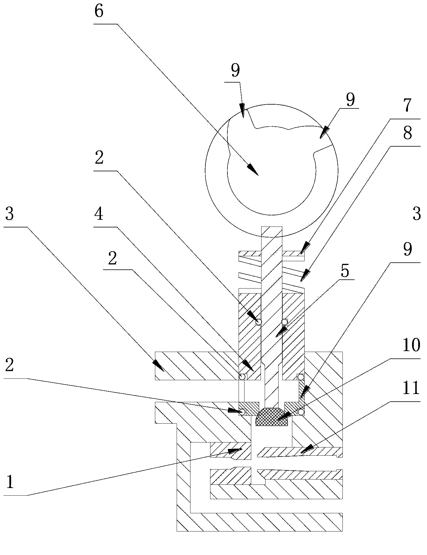
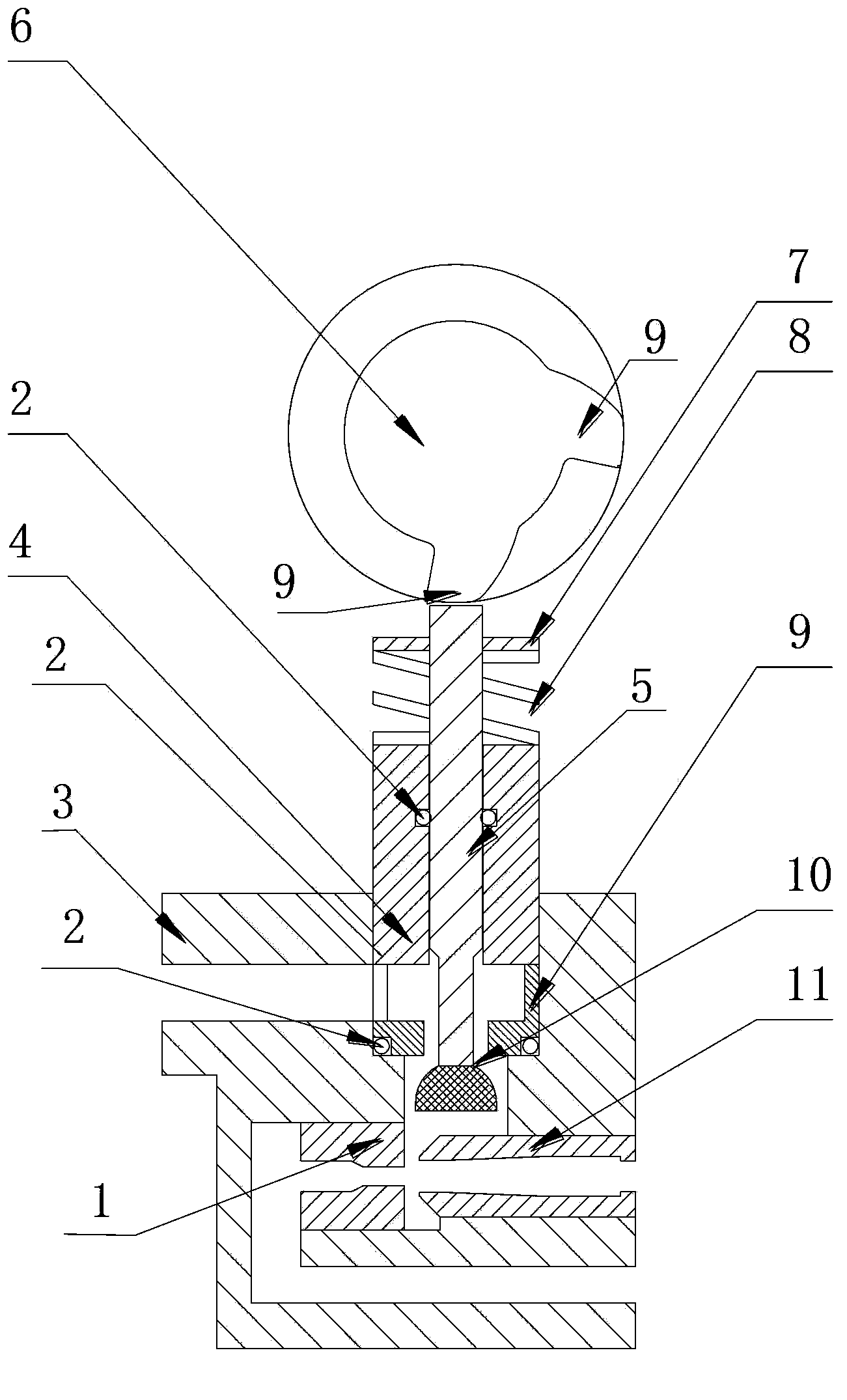
[0012] The present invention will be further described below in conjunction with the accompanying drawings.

[0013] Such as figure 1 with 2 As shown, a salt valve capable of automatically sucking salt and injecting water includes a salt valve body 3, a C-shaped passage is arranged inside the salt valve body 3, and the C-shaped passage is connected with the main valve, and the inside of the C-shaped passage A nozzle 1 and a throat 11 are provided. On the salt valve body 3 between the nozzle 1 and the throat 11, a 7-shaped flow channel communicating with the salt tank is provided. The 7-shaped flow channel includes a horizontal flow channel and a vertical flow channel. straight channel.

[0014] A vertical gap communicating with the outside world is provided at the corner of the 7-shaped flow channel, a piston assembly is installed in the gap, and the piston assembly includes a cavity 4, and a gap is arranged between the cavity 4 and the vertical gap. There is a sealing ring...


PUM


Abstract

The invention discloses a salt valve with automatic salt suction and water injection functions. A vertical notch communicated with the outside is formed in a runner of the salt valve. A piston component is mounted in the notch and comprises a cavity. An inner cavity of the cavity is of a through hole, and a piston rod and a piston head are arranged in the inner cavity. The piston head extends out to plug an opening at the bottom of the cavity. An opening allowing the runner of the salt valve to be communicated with the inner cavity of the cavity is formed in the side wall of the cavity. The head of the piston rod extends out of an opening at the top of the cavity. A groove is formed in the upper end of the piston rod. A press plate is clamped in the groove. A spring is pressed between the press plate and the upper end face of the cavity. A cam is arranged on the upper portion of the piston rod. A cam body is circular. Two same bosses radially protruding are arranged on the circular edge of the cam body at an interval. During operation, the cam rotates to drive a piston to open and close a channel in the salt valve. The channel is opened only during salt suction and water injection of the salt valve, and is closed to realize isolation from the outside when salt suction and water injection are not needed, so that mixed flow is avoided.

Description

technical field [0001] The invention relates to a liquid processing device, especially a liquid processing device with a salt valve. Background technique [0002] The salt valve in the liquid treatment device is usually placed on the side of the main valve, and there is a pipe connected to the main valve and the brine tank to perform the functions of salt absorption and water injection. When the treatment medium at the bottom of the main valve fails, brine needs to be sucked from the brine tank The treatment medium is regenerated. When the brine in the brine tank is used up, new salt particles need to be added and water is sucked from the main valve and injected into the brine tank through the salt valve to dissolve the salt particles to form brine. The middle channels of the existing salt valves are connected to each other. When the salt valve does not need to work, that is, when there is no need to absorb salt and inject water, if water is poured into the channel connected...

Claims


Application Information

Patent Timeline
Patent Type & Authority Applications(China)
IPC IPC(8): F16K1/14F16K1/36F16K31/524F16K27/02
CPCF16K27/0245F16K1/14F16K1/36F16K31/52408
Inventor 马旭光薛永
Owner NANJING FOBRITE ENVIRONMENTAL TECH
Why Eureka
Try Eureka