ct polarity tester

A tester and polarity technology, applied in the field of CT polarity tester, can solve problems such as current instability

Inactive Publication Date: 2017-11-17
HEBI POWER SUPPLY OF HENAN ELECTRIC POWERCORP
View PDF6 Cites 2 Cited by
  • Summary
  • Abstract
  • Description
  • Claims
  • Application Information

AI Technical Summary

Problems solved by technology

[0005] The purpose of the present invention is to provide a CT polarity tester to solve the problem of current instability in the CT polarity test

Method used


Image

  • ct polarity tester
  • ct polarity tester
  • ct polarity tester

Examples


Embodiment Construction

[0025] The present invention will be further described in detail below through specific embodiments in conjunction with the drawings.

[0026] Taking into account the current instability of current CT polarity testers, the present invention provides a CT polarity tester.

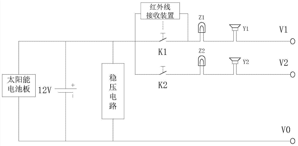
[0027] It includes: a power supply circuit, a voltage stabilizing circuit, an output circuit, and an infrared remote control circuit; where the power supply circuit includes: a solar panel and a battery connected in series; the positive and negative electrodes of the battery are connected to the output circuit; the output circuit includes: A connecting wire and a second connecting wire connected to the negative electrode of the battery. The first connecting wire includes a first output circuit and a second output circuit connected in parallel. The first positive terminal is arranged on the first output circuit, and the second positive terminal is arranged on the On the second output line; the second connection li...


PUM


Abstract

The invention relates to the field of relay protection of power systems, in particular to a CT polarity tester. It includes: a power supply circuit, a voltage stabilizing circuit, an output circuit, and an infrared remote control circuit; among them, the power supply circuit includes: solar panels and batteries connected in series; the positive and negative poles of the battery are connected to the output circuit; the output circuit includes: A connection line, a second connection line connected to the negative pole of the storage battery, the first connection line includes the first positive terminal and the second positive terminal connected in parallel, the second connection line includes the first negative terminal; the two ends of the voltage stabilizing circuit are respectively The first connection line and the second connection line are connected; the infrared remote control circuit is connected to the output circuit. The invention can form a stable input voltage and obtain accurate test results.

Description

Technical field [0001] The invention relates to the field of power system relay protection, in particular to a CT polarity tester. Background technique [0002] The power grid has new and expanded substation projects every year. The correctness of CT polarity and its secondary circuit verification directly affects the correct operation of the protection device, and the accurate operation of the measurement and metering devices. It has become an important and important part of the new and expanded power grid. An indispensable job. At the same time, the correct action of the protection device is directly related to the smooth commissioning of the new and expanded stations, the stable operation in the future, and the stable operation of the regional power grid. Therefore, it is particularly critical to ensure the correctness of the CT polarity and secondary circuit of the power system. In practical engineering applications, CT polarity and its secondary circuit inspection equipmen...

Claims


Application Information

Patent Timeline
Patent Type & Authority Patents(China)
IPC IPC(8): G01R31/06
Inventor 刘洋魏帅齐刘锋佟建炜秦晓波李晓燕刘思青张红娜郝学敏
Owner HEBI POWER SUPPLY OF HENAN ELECTRIC POWERCORP
Why Eureka
Try Eureka