Spotlight mode direct-looking synthetic aperture imaging lidar

A technology of synthetic aperture laser and imaging radar, which is applied in the direction of instruments, measuring devices, and using re-radiation, can solve the problem of direct-viewing synthetic aperture laser imaging radar without spotlight mode, so as to improve the along-track imaging resolution and high Effect of Receive Sensitivity

Active Publication Date: 2017-02-15
SHANGHAI INST OF OPTICS & FINE MECHANICS CHINESE ACAD OF SCI
View PDF3 Cites 0 Cited by
  • Summary
  • Abstract
  • Description
  • Claims
  • Application Information

AI Technical Summary

Problems solved by technology

Direct-looking SAR in strip scanning mode has been developed so far (References 1-5), but there is no direct-looking SAR in spotlight mode

Method used


Image

  • Spotlight mode direct-looking synthetic aperture imaging lidar
  • Spotlight mode direct-looking synthetic aperture imaging lidar
  • Spotlight mode direct-looking synthetic aperture imaging lidar

Examples


Embodiment Construction

[0036] The present invention will be described in further detail below in conjunction with the accompanying drawings and embodiments, but the protection scope of the present invention should not be limited thereby.

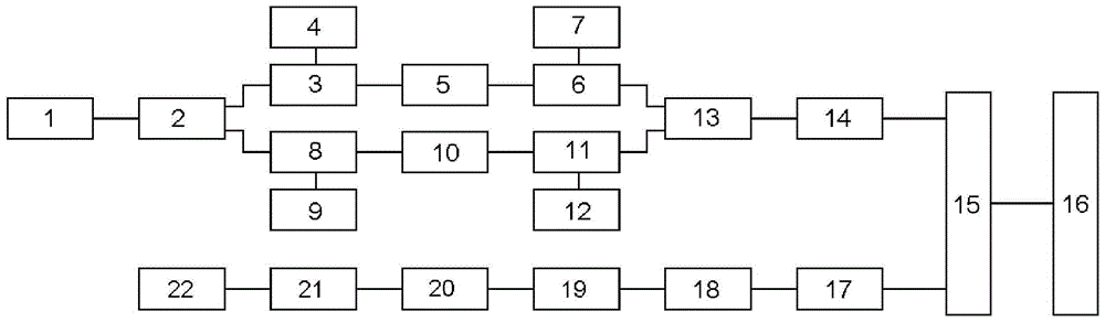
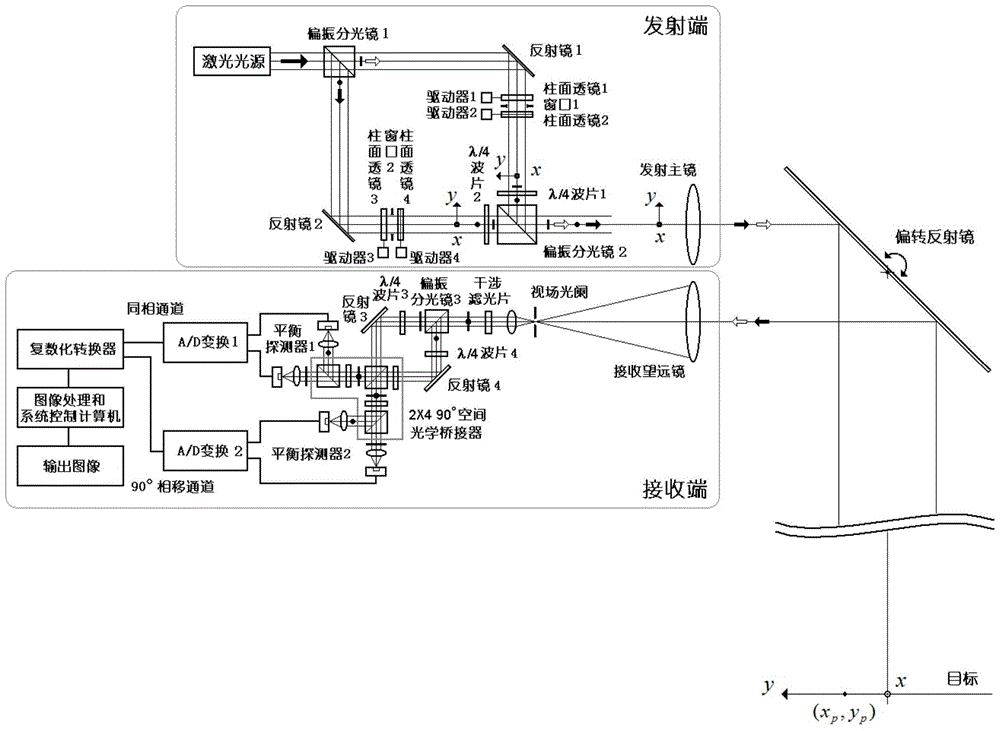
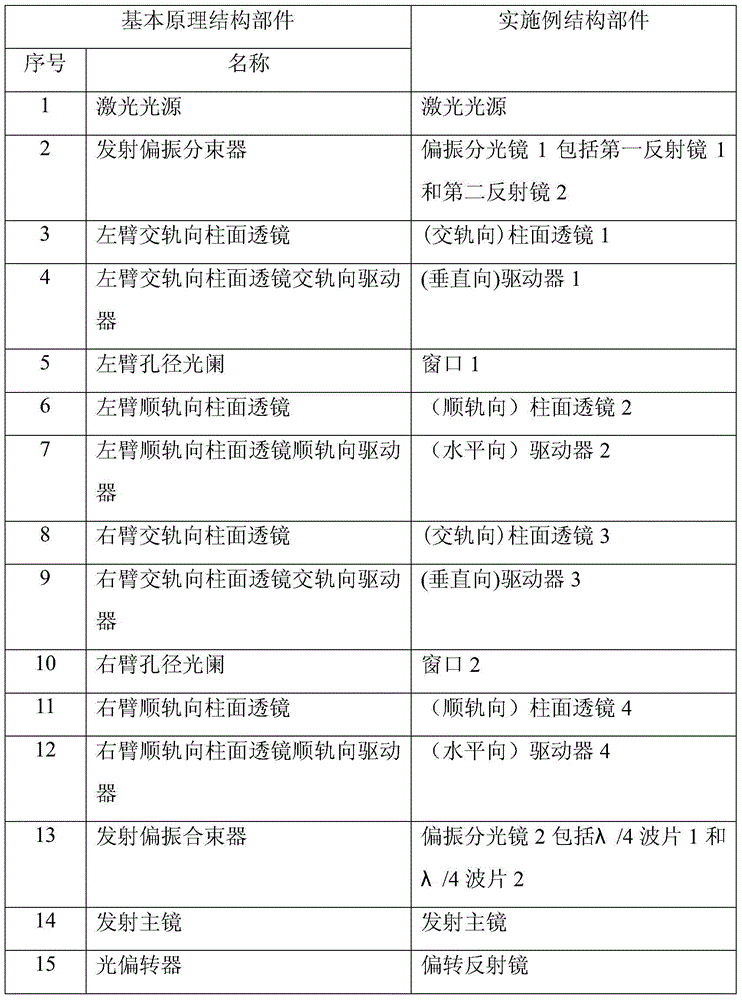
[0037] see first figure 1 , figure 1 It is a principle diagram of the spotlight mode direct-looking synthetic aperture laser imaging radar of the present invention. It can be seen from the figure that the beamforming mode direct-looking synthetic aperture laser imaging radar of the present invention is composed of a transmitting end, a receiving end and an optical deflector. Cylindrical lens 3, left arm cross-track cylindrical lens cross-track driver 4, left arm aperture stop 5, left arm follow-track cylindrical lens 6, left arm follow-track cylindrical lens drive 7 , right arm cross-track cylindrical lens 8, right arm cross-track cylindrical lens cross-rail driver 9, right arm aperture stop 10, right arm along-track cylindrical lens 11, right arm along-track cy...


PUM


Abstract

A spotlight mode down-looking synthetic aperture laser imaging radar structurally comprises a laser source, an emission polarization beam splitter, a left arm cross-rail cylindrical lens, a left arm cross-rail cylindrical lens cross-rail driver, a left arm aperture diaphragm, a left arm along-rail cylindrical lens, a left arm along-rail cylindrical lens along-rail driver, a right arm cross-rail cylindrical lens, a right arm cross-rail cylindrical lens cross-rail driver, a right arm aperture diaphragm, a right arm along-rail cylindrical lens, a right arm along-rail cylindrical lens along-rail driver, an emission polarization beam combiner, a main emission mirror, a receiving telescope, a polarization interference autodyne same-phase and 90-degree phase-shift two-channel photoelectric receiver, an AD converter, a pluralized converter, an image processing and system control computer and an optical deflector. Compared with a down-looking synthetic aperture laser imaging radar in a stripe scanning mode, the spotlight mode down-looking synthetic aperture laser imaging radar has very high system receiving flexibility and along-rail imaging resolution and is particularly suitable for application to large optical footprints and remote targets.

Description

technical field [0001] The invention relates to a synthetic aperture laser imaging radar, which is a spotlight mode direct-looking synthetic aperture laser imaging radar. In principle, the optical deflector is used to make the direct-looking synthetic aperture imaging lidar move in a straight line, and its optical foothold is fixed to point to the target area of ​​interest. Make synchronous movement, and move along the track to the phase quadratic term wave front in the relatively static state of the optical foot site, and obtain the phase quadratic term history of the target. In the cross-track direction, the method of obtaining the linear phase modulation item of the target lateral range by the direct-looking synthetic aperture imaging lidar is still retained. The target imaging algorithm adopts the traditional cross-track Fourier transform focusing and along-track conjugate phase quadratic term matched filter focusing algorithm. Compared with the direct-looking synthetic ...

Claims


Application Information

Patent Timeline
Patent Type & Authority Patents(China)
IPC IPC(8): G01S17/89G01S7/481G01S7/483
CPCG01S7/481G01S17/90
Inventor 刘立人
Owner SHANGHAI INST OF OPTICS & FINE MECHANICS CHINESE ACAD OF SCI
Why Eureka
Try Eureka