Diffracted wave imaging method and diffracted wave imaging device based on dynamical features

A dynamic feature and diffraction wave technology, applied in the field of seismic exploration, can solve problems such as not being able to deal with diffraction wave imaging problems well

Active Publication Date: 2014-12-24
PETROCHINA CO LTD
View PDF6 Cites 32 Cited by
  • Summary
  • Abstract
  • Description
  • Claims
  • Application Information

AI Technical Summary

Problems solved by technology

The basic diffraction is only a mathematical approximation, and there is a big difference in the dynamic characteristics of the real diffraction wave in the underground space. Therefore, it cannot handle the diffraction wave imaging problem well.

Method used


Image

  • Diffracted wave imaging method and diffracted wave imaging device based on dynamical features
  • Diffracted wave imaging method and diffracted wave imaging device based on dynamical features
  • Diffracted wave imaging method and diffracted wave imaging device based on dynamical features

Examples


Embodiment

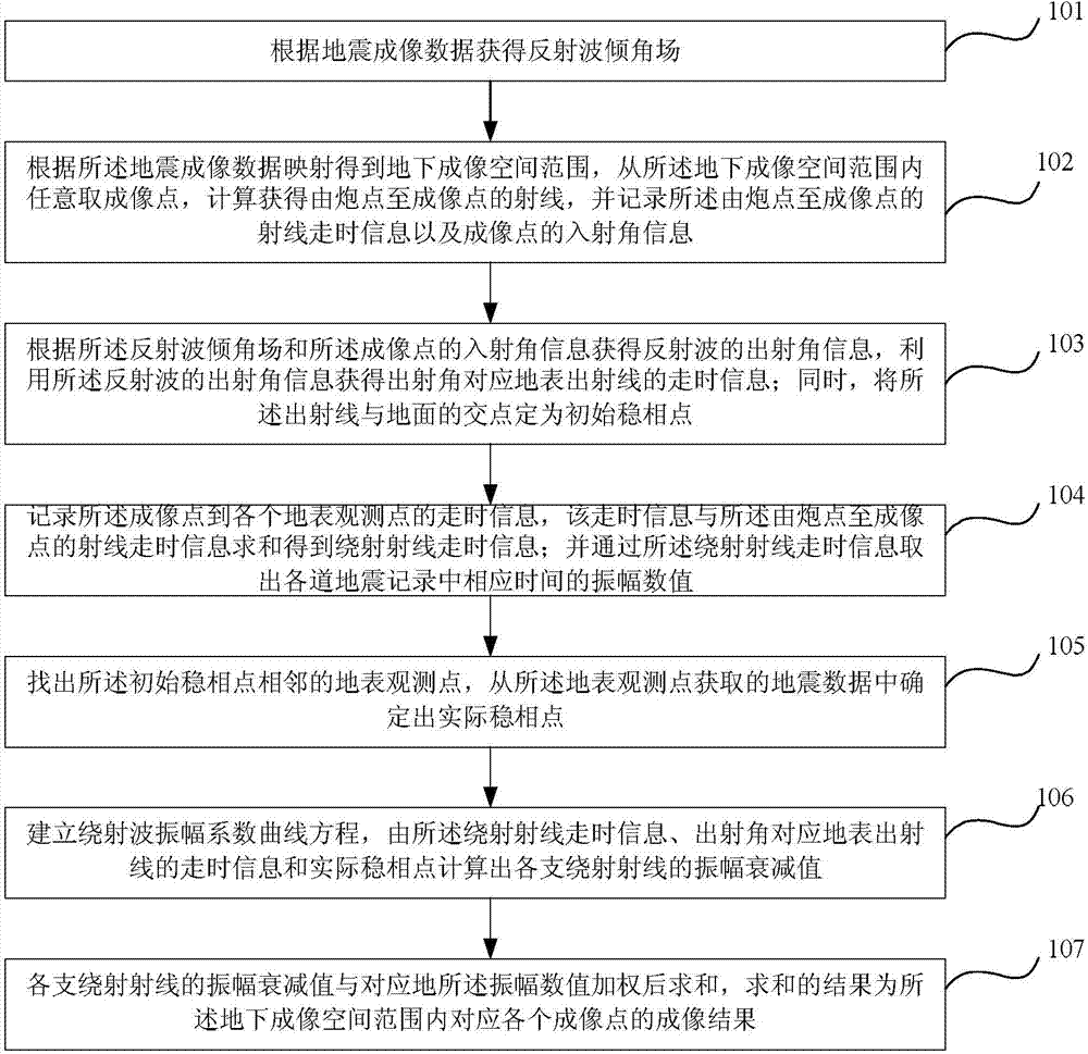
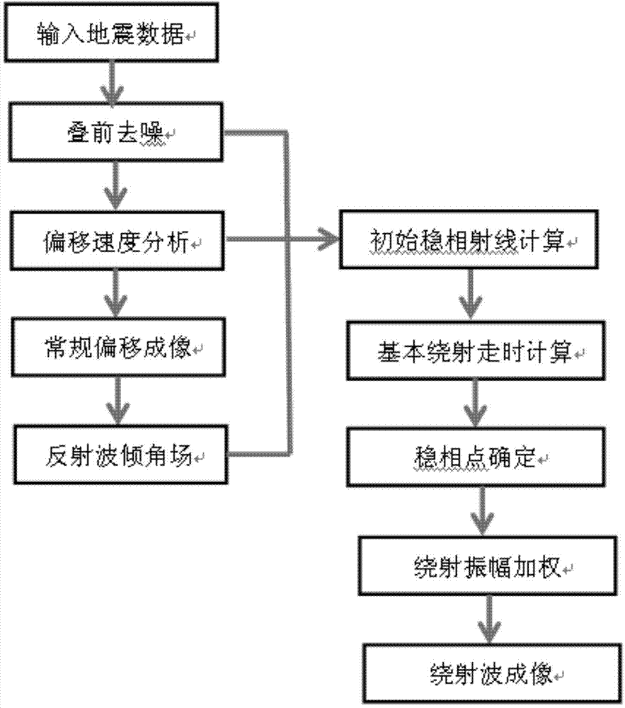
[0120] Through the analysis of seismic data collected in the field, the application effect of the diffraction wave imaging method based on dynamic characteristics in the imaging of discontinuous geological bodies such as fractures and small faults is illustrated. The specific technical process is as follows: image 3 shown.

[0121] (1) Seismic records are collected by receiving observations on both sides of the shot in the middle. The number of seismic receiving channels is 480, the channel spacing is 10 meters, the number of time samples is 1251, and the interval is 4 milliseconds. The preprocessing stage needs to remove surface waves, refracted waves, direct waves, etc. interference wave, the single-shot record shown as Figure 4a As shown, the development characteristics of diffraction waves in seismic data are obvious.

[0122] (2) Use the given migration velocity field to obtain conventional seismic imaging results, such as Figure 4b As shown, the reflected wave incli...


PUM


Abstract

The invention relates to a diffracted wave imaging method and a diffracted wave imaging device based on dynamical features. The diffracted wave imaging method comprises the following steps of acquiring a reflected wave inclination field according to earthquake imaging data; optionally taking an imaging point and recording travel time information of a ray from a shot point to the imaging point and the information of incident angle of the imaging point; acquiring travel time information of a ground surface emergent ray corresponding to an emergent angle; setting an intersection point of the emergent ray and the ground as an initial stationary phase point; recording travel time information from the imaging point to various ground surface observation points; summing the travel time information and the travel time information of the ray from the shot point to the imaging point so as to obtain travel information of a diffraction ray; taking out an amplitude numerical value of corresponding time in various earthquake records and determining an actual stationary phase point; establishing a diffracted wave amplitude coefficient curvilinear equation; acquiring an amplitude attenuation value of a diffraction ray according to the travel time information of the diffraction ray, the travel time information of the emergent angle corresponding to the ground surface emergent ray and the actual stationary phase point; and performing summing after weighting the amplitude attenuation value of the diffraction ray and a corresponding ground amplitude numerical value so as to obtain imaging results of various corresponding imaging points in an underground imaging space range.

Description

technical field [0001] The invention relates to the field of seismic exploration, belongs to the technical category of seismic data imaging, and in particular relates to a diffraction wave imaging method and device based on dynamic characteristics. Background technique [0002] With the development of oil and gas field exploration and development, the detection of small-scale geological bodies has attracted more and more attention from the industry. Such geological anomalies usually exist in seismic data as diffracted waves. Therefore, mining useful diffraction information from seismic data has important application value in production. At present, seismic exploration is mainly based on reflection exploration, which cannot break through the limitation of the Ruili criterion, so it cannot effectively identify such geological bodies. [0003] Essentially, diffracted waves are carriers of seismic wave information for these complex structural geological anomalies. Complex res...

Claims


Application Information

Patent Timeline
Patent Type & Authority Applications(China)
IPC IPC(8): G01V1/28
Inventor 赵惊涛李明张研李洪辉周波
Owner PETROCHINA CO LTD
Why Eureka
Try Eureka