
Workpiece collaborative machining method and system and collaborative control method and device

A technology of workpiece and workpiece coordinates, applied in the direction of digital control, electrical program control, etc., can solve the problems that it is difficult to realize the synchronous control movement of mechanical unit A, the difficulty of motion trajectory, and the difficulty of interpolation, so as to achieve low interpolation difficulty and synchronization The effect of improved control movement and simple movement trajectory

Inactive Publication Date: 2014-12-24
BEIJING A&E TECH
View PDF4 Cites 10 Cited by
  • Summary
  • Abstract
  • Description
  • Claims
  • Application Information

AI Technical Summary

Problems solved by technology

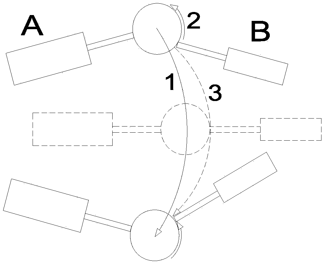
[0004] The inventors of the present application have discovered in long-term research and development that since mechanical unit A follows a movement trajectory, mechanical unit B also follows a movement trajectory relative to A, and mechanical unit B will follow a complex movement trajectory of unknown geometry relative to the world coordinate system. Synthesizing the motion trajectory of mechanical unit B relative to the world coordinate system in the prior art is relatively difficult and has low practicability; in addition, since the motion trajectory of mechanical unit B relative to the world coordinate system is relatively complicated, if the synthetic motion trajectory is compared with the world coordinate system The position of mechanical unit B at each interpolation moment is obtained by interpolation, so as to ensure the movement trajectory of mechanical unit B in the workpiece coordinate system that moves with mechanical unit A, and the interpolation difficulty will be correspondingly greater, that is, it is difficult to realize the mechanical unit B. Synchronous control movement of A and B

Method used


Image

  • Workpiece collaborative machining method and system and collaborative control method and device
  • Workpiece collaborative machining method and system and collaborative control method and device
  • Workpiece collaborative machining method and system and collaborative control method and device

Examples


no. 1 approach

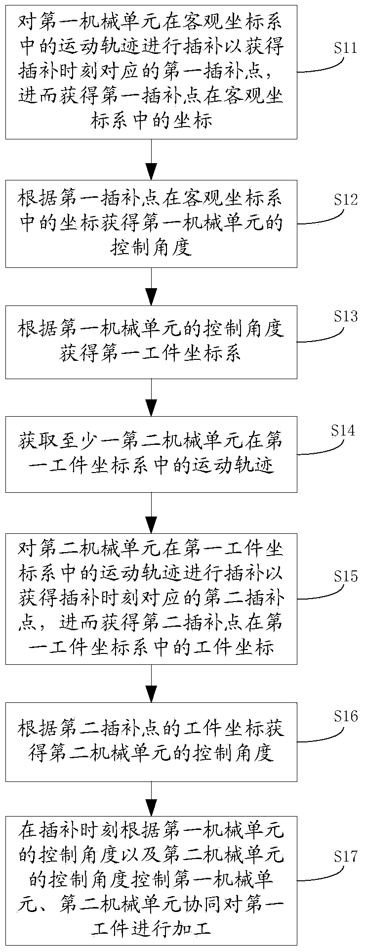
[0025] See figure 2 , The first embodiment of the collaborative processing method of the workpiece of the present invention includes:

[0026] Step S11: Interpolate the movement track of the first mechanical unit in the objective coordinate system to obtain the first interpolation point corresponding to the interpolation time, and then obtain the coordinates of the first interpolation point in the objective coordinate system.

[0027] Interpolate the motion track of the first mechanical unit in the objective coordinate system to obtain the first interpolation point corresponding to the interpolation time t, and then obtain the coordinates of the first interpolation point in the objective coordinate system. Interpolation is the process of obtaining the interpolation point located in the middle of the known point according to the interpolation algorithm according to some points on the motion trajectory. The interpolation point corresponding to the interpolation time t is the tool cen...

no. 2 approach

[0052] See Figure 4 , The second embodiment of the collaborative processing method of the workpiece of the present invention includes:

[0053] Step S21: Interpolate the movement track of the first mechanical unit in the objective coordinate system to obtain the first interpolation point corresponding to the interpolation time, and then obtain the coordinates of the first interpolation point in the objective coordinate system.

[0054] In this embodiment, the objective coordinate system is a coordinate system that is stationary with respect to the world coordinate system. Further, the coordinate system that is stationary with respect to the world coordinate system is specifically a workpiece coordinate system that is stationary with respect to the world coordinate system.

[0055] Step S22: Obtain the control angle of the first mechanical unit according to the coordinates of the first interpolation point in the objective coordinate system.

[0056] In this embodiment, the coordinates ...


PUM


Abstract

The invention discloses a workpiece collaborative machining method. The workpiece collaborative machining method comprises the steps that interpolation is carried out on the motion trail of a first mechanical unit in an objective coordinate system so that a first interpolation point can be obtained, and then the control angle of the first mechanical unit and a first workpiece coordinate system are obtained; interpolation is carried out on the motion trail of a second mechanical unit in the first workpiece coordinate system so that a second interpolation point corresponding to the interpolation moment can be obtained, and then the workpiece coordinates of the second interpolation point in the first workpiece coordinate system are obtained; the control angle of the second mechanical unit is obtained according to the workpiece coordinates of the second interpolation point; the first mechanical unit and the second mechanical unit are controlled to collaboratively machine a first workpiece at the interpolation moment according to the control angle of the first mechanical unit and the control angle of the second mechanical unit. The invention further discloses a workpiece collaborative machining system and a collaborative control method and device for multiple mechanical units. According to the workpiece collaborative machining method and system and the collaborative control method and device for multiple mechanical units, synchronous control over the multiple mechanical units can be easily achieved so that the machining efficiency can be improved, and practicability is high.

Description

Technical field [0001] The present invention relates to the industrial field, in particular to a method and system for collaborative processing of workpieces and a method and device for collaborative control of multiple mechanical units. Background technique [0002] In the control of mechanical units such as industrial robots, multiple mechanical units are often required to cooperate to complete a task. For example: a robot grabs a workpiece that moves with a conveyor belt; an arc welding robot responds to a workpiece that moves with a positioner. The workpiece is subjected to arc welding operations, and a spot welding robot performs spot welding operations on a workpiece that is grabbed by another robot and moved with it. In the above application scenarios of multiple mechanical units, they have the common feature that one mechanical unit carries the workpiece for a basic movement, and the other mechanical unit superimposes another movement on the basis of the movement of the w...

Claims


Application Information

Patent Timeline
Patent Type & Authority Applications(China)
IPC IPC(8): G05B19/4103
CPCG05B19/4103
Inventor 叶根
Owner BEIJING A&E TECH
Learn More