
Electrical connector for circuit board and electrical connector installation body

A technology for circuit substrates and electrical connectors, which is applied in the direction of protective grounding/shielding devices of connecting parts, components of connecting devices, circuits, etc., can solve problems such as electrical short circuit of pads

Active Publication Date: 2014-12-24
HIROSE ELECTRIC GROUP
View PDF6 Cites 18 Cited by
  • Summary
  • Abstract
  • Description
  • Claims
  • Application Information

AI Technical Summary

Problems solved by technology

However, in this case, in the above-mentioned central area, the ground leg of the housing is located between the ground terminal and the signal terminal adjacent to the ground terminal, so that the ground leg is too close to the signal connection portion of the signal terminal.
Therefore, on the circuit board, correspondingly, the ground pads for connecting the above-mentioned ground pins and the signal pads for connecting the above-mentioned signal connection parts are formed at positions that are too close to each other. Therefore, when mounting the connector, The soldering of the respective pads is connected to each other, causing the two pads to be electrically shorted to each other

Method used


Image

  • Electrical connector for circuit board and electrical connector installation body
  • Electrical connector for circuit board and electrical connector installation body
  • Electrical connector for circuit board and electrical connector installation body

Examples


Embodiment Construction

[0031] Embodiments of the present invention will be described below based on the drawings.

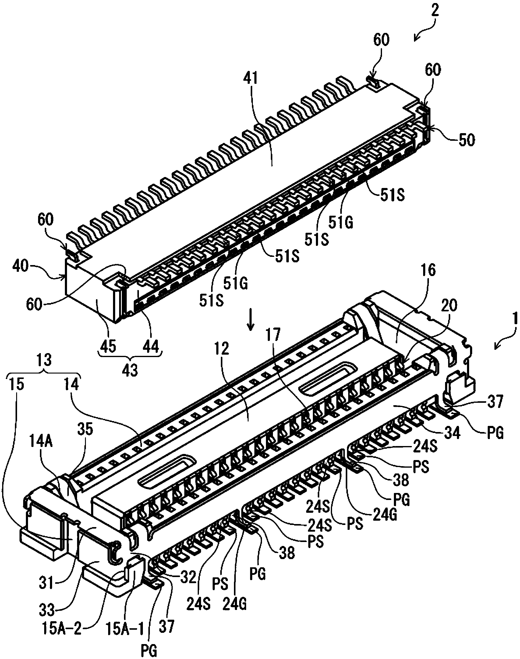
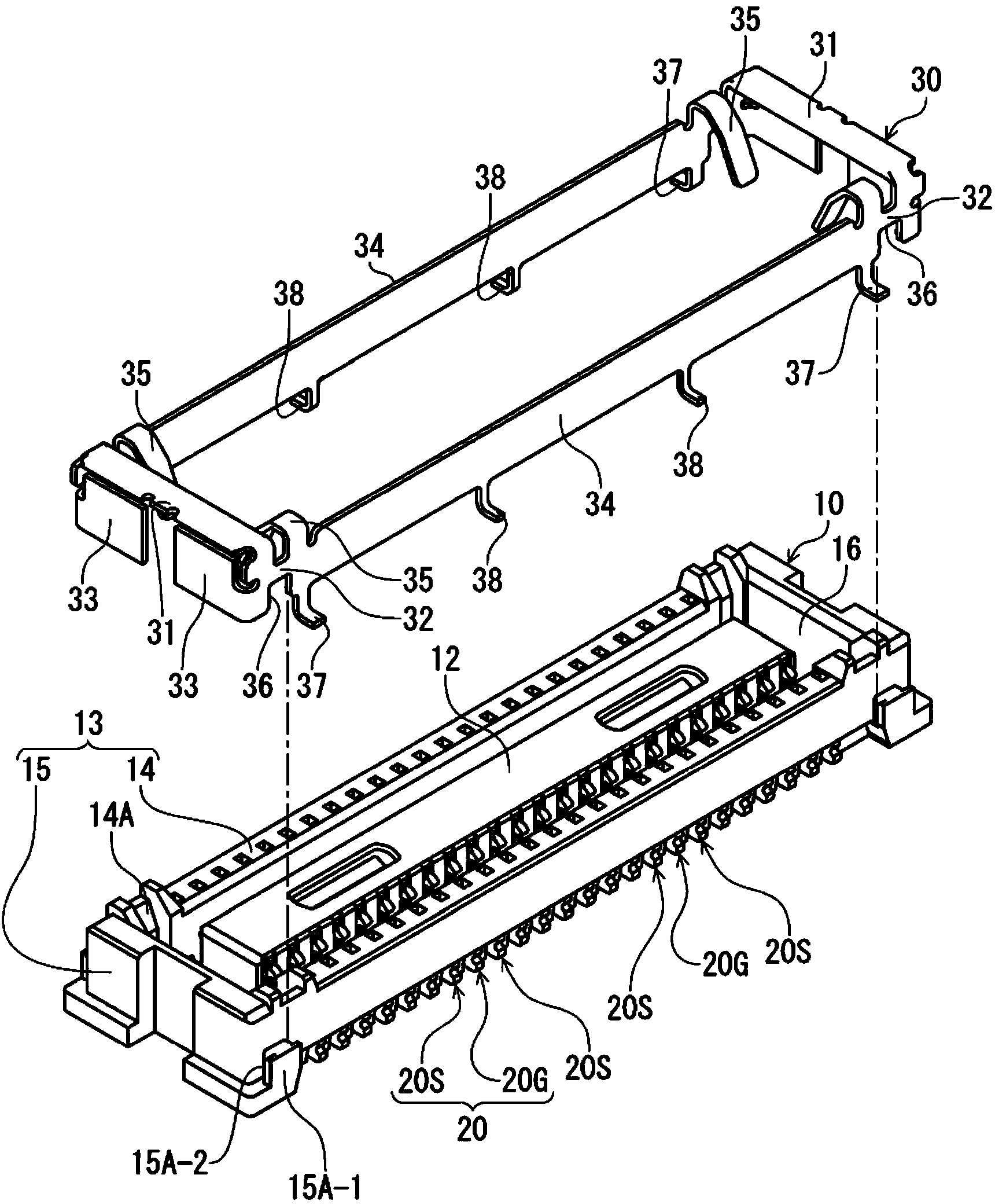
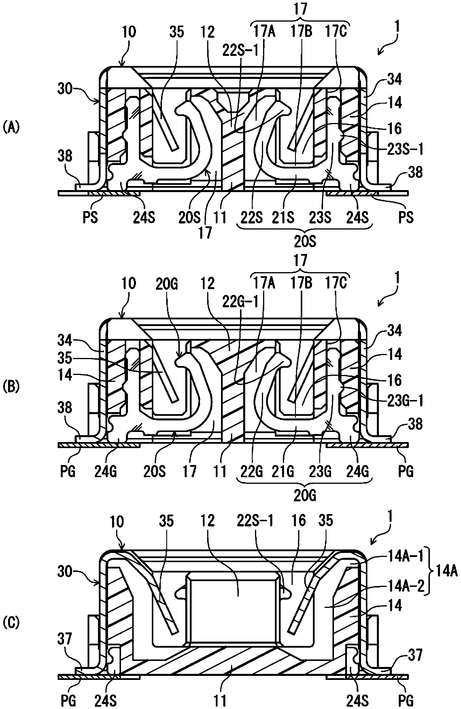
[0032] figure 1 It is a perspective view showing the receptacle connector 1 according to the embodiment of the present invention together with a plug connector 2 as a mating connector, and shows a state before the connectors are fitted. figure 2 is showing figure 1 A perspective view of a state before installation of the shield member 30 of the receptacle connector 1 . image 3 yes figure 1 The cross-sectional view of the receptacle connector 1 on the surface at right angles to the terminal arrangement direction, image 3 (A) shows a cross section at the position of the signal terminal 20S, image 3 (B) shows a cross section at the position of the ground terminal 20G, image 3 (C) is a cross section at the position of the contact piece 35 of the shield member 30 .

[0033] The receptacle connector 1 of the present embodiment and the plug connector 2 as the mating connector of th...


PUM


Abstract

The invention provides an electrical connector for a circuit board and an electrical connector installation body. The electrical connector cannot be enlarged in a terminal arrangement direction and can carry out reliable connection of a connection section of each terminal and a grounding pin section of a shield section with corresponding bonding pads. A grounding connection section (24G) of a grounding terminal (20G) is located between the signal connection sections (24S) of two adjacent signal terminals (20) in the terminal arrangement direction. The grounding pin section (38) of the shield section (30) is connected with a bonding pad for grounding and of the circuit board in a position closer than the above signal connection section (24S) and the above grounding section (24) in the connector width direction, is located in a region between the signal connection sections (24S) at two sides of the grounding connection section (24G) corresponding to the grounding pin section (38), and has an overlapping range with the grounding connection section (24G) in the terminal arrangement direction.

Description

technical field [0001] The present invention relates to an electrical connector for a circuit board disposed on a circuit board, and an electrical connector mounting body in which the circuit board electrical connector is mounted on the circuit board. Background technique [0002] As such a connector, for example, an electrical connector for a circuit board disclosed in Patent Document 1 is known. Patent Document 1 discloses an electrical connector for a circuit board that is arranged on a circuit board and is fitted and connected to a mating connector from above. This electrical connector for a circuit board has: a thin, substantially rectangular parallelepiped housing extending in a direction parallel to the circuit board as a longitudinal direction; a plurality of terminals; and two shells (shield parts) mounted on the housing. [0003] The housing has two side walls extending along the terminal arrangement direction and opposing in the connector width direction (a dire...

Claims


Application Information

Patent Timeline
IPC IPC(8): H01R13/648H01R13/652H01R13/502H01R12/57
CPCH01R12/57H01R12/72H01R13/648
Inventor 和田慎司绿川和弥
Owner HIROSE ELECTRIC GROUP
Learn More