Compression mat for an electrical connector

a compression mat and connector technology, applied in the direction of fixed connections, coupling device connections, printed circuit aspects, etc., can solve the problems of ineffective increase of the strength of the pillars to resist buckling, poor or no electrical connection between the contacts, and side contact between adjacent pillars, so as to minimize the tendency of the pillars to buckle. , the effect of reliably applying a spring for

Inactive Publication Date: 2008-09-16
AMPHENOL CORP
View PDF31 Cites 33 Cited by
  • Summary
  • Abstract
  • Description
  • Claims
  • Application Information

AI Technical Summary

Benefits of technology

[0009]The invention is an improved electrical connector having a compression mat that reliably applies a spring force to a large number of closely spaced electrical contacts. The compression mat minimizes the tendency of the pillars to buckle and interfere with each other when the spring is compressed.

Problems solved by technology

The buckled pillars apply insufficient spring force to the contacts, and poor or no electrical connections are made between the contacts.
Increasing the strength of the pillars to resist buckling is ineffective.
If the pillars are too closely spaced together, the sides of adjacent pillars contact and interfere with each other as the spring is compressed.
The interference prevents the pillars from applying sufficient spring force to the contacts, and poor or no electrical connections are made between the contacts.
This makes it more difficult to design a compression mat that can reliably apply a spring force to a large number of contacts without the pillars buckling or without the pillars interfering with one another.

Method used


Image

  • Compression mat for an electrical connector
  • Compression mat for an electrical connector
  • Compression mat for an electrical connector

Examples


first embodiment

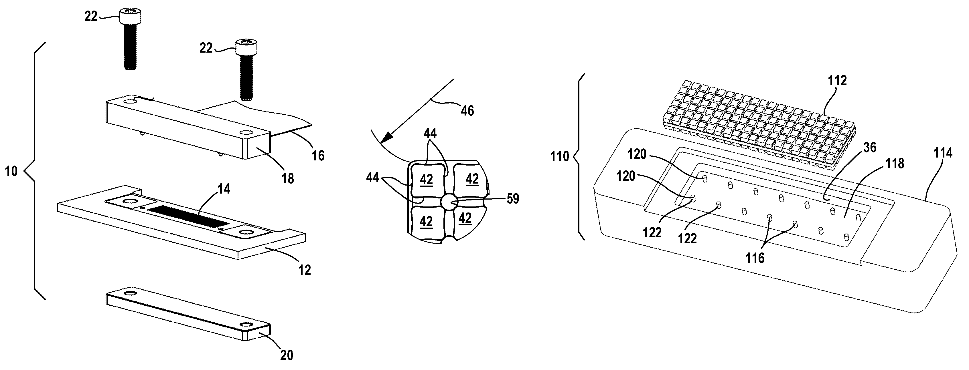
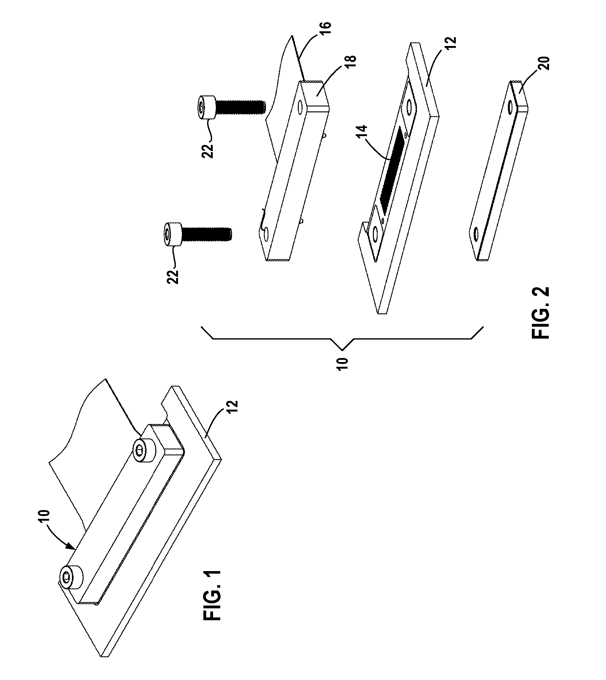
[0031]FIGS. 1 and 2 illustrate a first embodiment electrical connector 10 in accordance with the present invention that forms electrical interconnections with a printed circuit board 12. Circuit board 12 has a contact field 14 on one side of the circuit board that electrically interconnects the circuit board with the electrical connector 10. Contact field 14 has a large number of closely spaced electrical contacts arranged in rows and columns. The illustrated contact field 14 has three hundred contacts arranged in six rows and fifty columns.

[0032]Electrical connector 10 includes a flexible circuit 16, a support member or clamp 18 attached to an end of the flexible circuit 16, and a backing member 20. Fasteners 22 extend through holes in the clamp 18 and the circuit board 12, and thread into the backing member 20 to connect the electrical connector 10 to the circuit board 12.

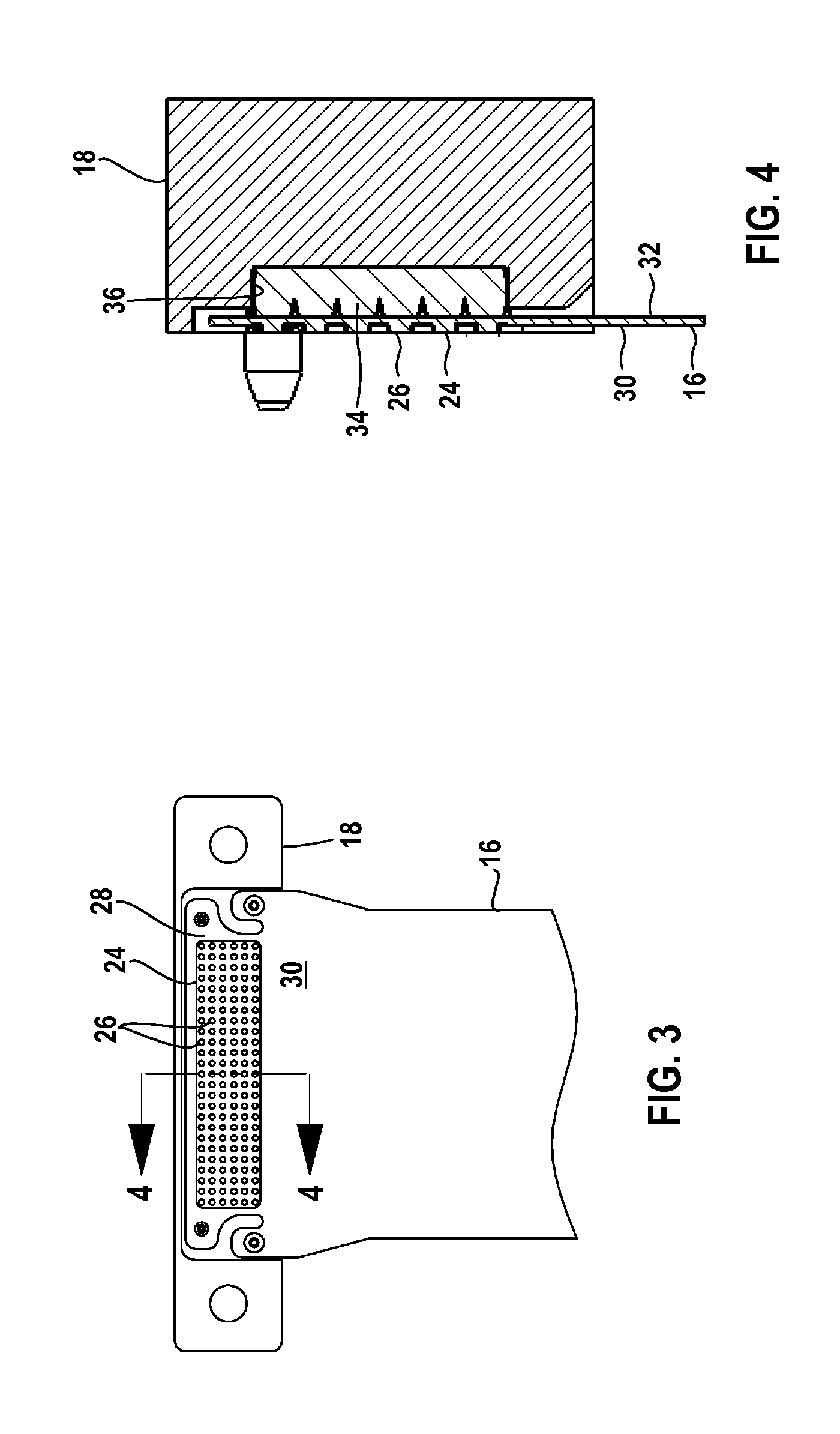
[0033]FIGS. 3 and 4 illustrate the flexible circuit 16 and clamp 18. Flexible circuit 16 has a contact field 2...

second embodiment

[0042]The bridges 52, 54 extend only between facing sides of the pillars 42. As a result, the pillars 42 and bridges 52, 54 define regularly spaced rows and columns of uniformly sized passages or through-holes 59 that extend the thickness of the mat 34. Each hole 59 is surrounded by four adjacent pillars 42, as best shown in FIG. 8. The shape or profile of the pillars 42 and bridges 52, 54 define the shapes of the holes 59. In the illustrated embodiment the pillars 42 and bridges 52, 54 have rounded or chamfered corners to define substantially circular holes 59. Holes 59 can be used to accurately position and retain the compression mat 34 in the clamp compartment 36 as will be described in greater detail below with reference to a second embodiment electrical connector.

[0043]FIG. 10 illustrates an interior portion of the compression mat 34, with an interior pillar 42a located in row 48a and column 50a. Pillar 42a is between two pillars 42b, 42c in row 48a and between two pillars 42d,...


PUM


Abstract

An electrical connector assembly includes a flexible circuit attached to a clamp member and a compression mat between the clamp member and the flexible circuit. The compression mat has a number of spaced-apart pillars that overlay contacts of the flexible circuit. The pillars are interconnected by sets of upper and lower bridges, with each set of bridges interconnecting some, but not all, the pillars. Each pillar has a rectangular cross section with concave sides.

Description

FIELD OF THE INVENTION[0001]The invention relates to an electrical connector having a flexible circuit for forming electrical connections between closely spaced contacts of the flexible circuit and closely spaced contacts of a circuit board, and particularly to a compression mat or pressure pad for the electrical connector.BACKGROUND OF THE INVENTION[0002]Electrical connectors are used to form electrical connections between circuit boards that each contains a high density of electrical contacts. The contacts are arranged in a series of rows and columns in a contact field on one side of the circuit board. The contacts are closely spaced and a large number of contacts are included in a relatively small area.[0003]One type of high-density electrical connector includes a flexible circuit having a contact field located on one side of the flexible circuit. The contact field includes contacts for electrically interconnecting the flexible circuit with another contact field. The flexible cir...

Claims


Application Information

Patent Timeline
Patent Type & Authority Patents(United States)
IPC IPC(8): H01R12/00
CPCH01R12/62H05K3/365H01R13/2414H05K2201/10393
Inventor TAYLOR, PAUL R.
Owner AMPHENOL CORP
Why Eureka
Try Eureka