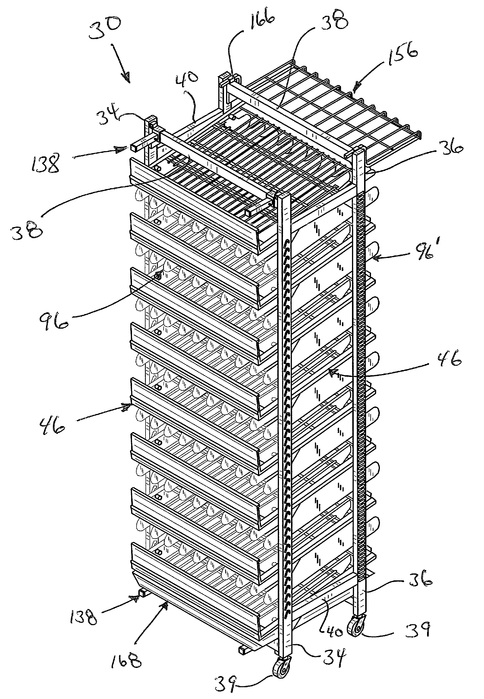
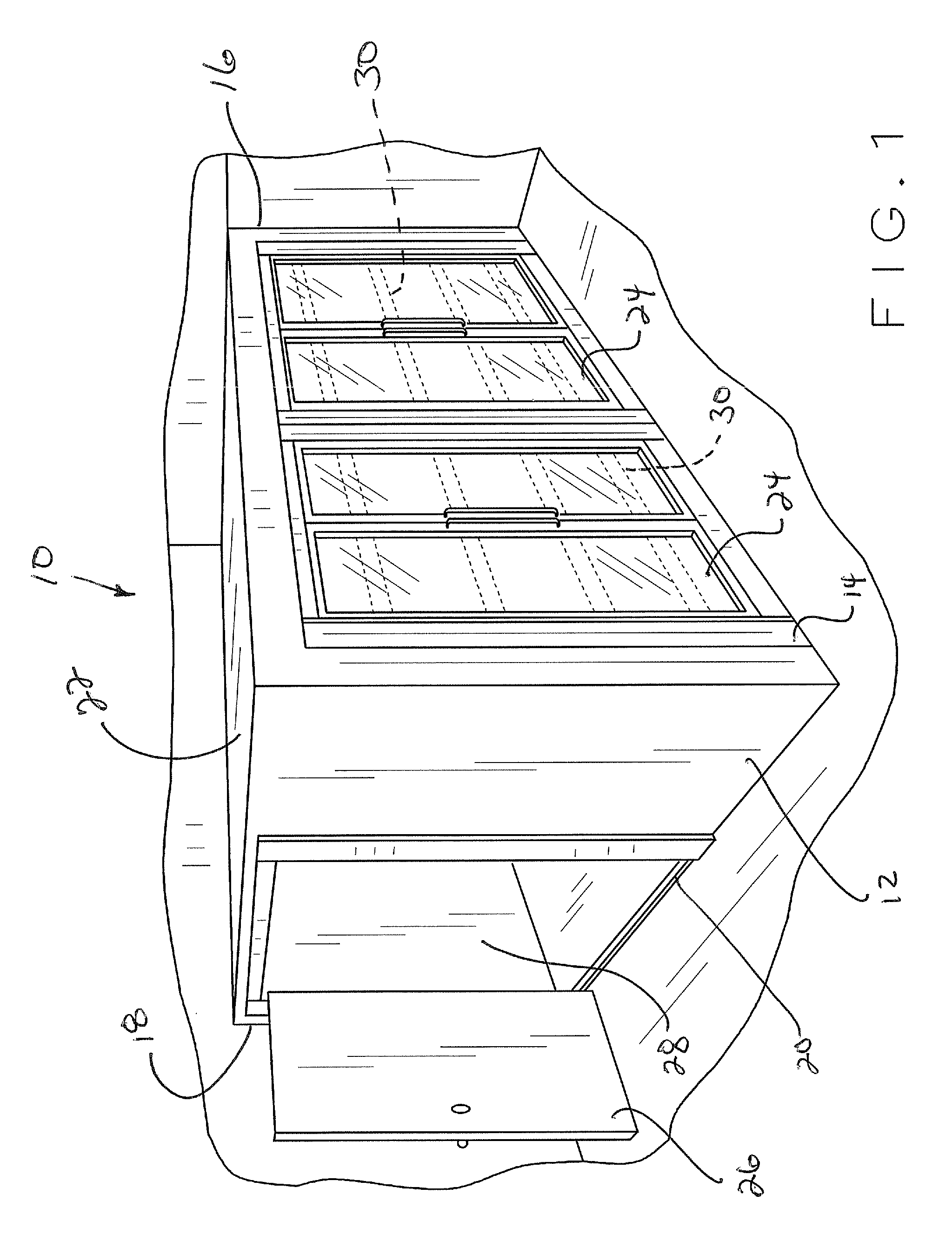
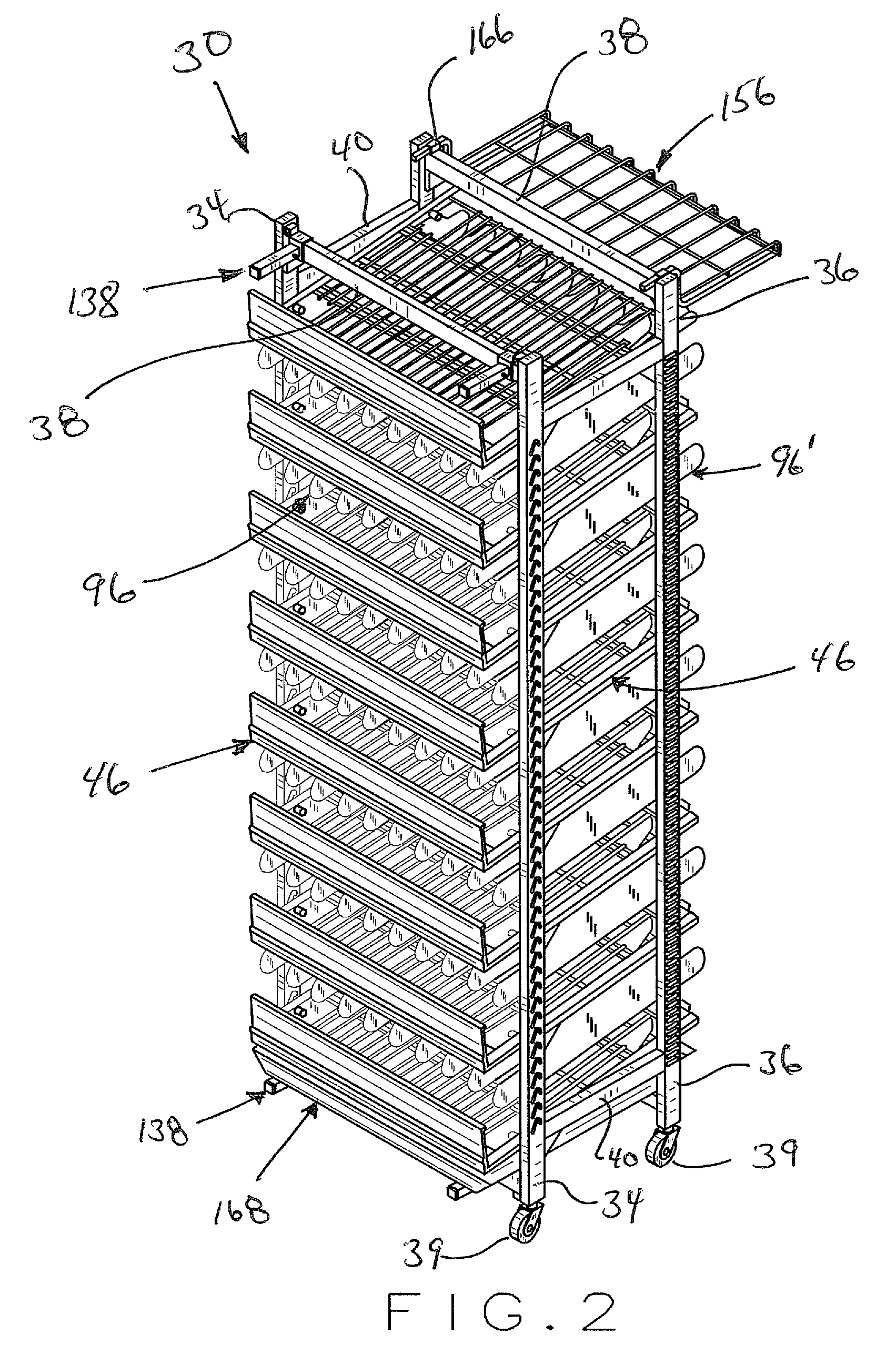
[0007]The present invention relates to a product merchandising
system for use in walk-in display coolers and the like, or other product merchandising areas, wherein the present
system includes a framework structure adaptable for adjustably positioning a plurality of individual shelf members therebetween, the framework structure being either non-movable or positioned on a plurality of casters or other wheel means for freely moving the entire system into and / or out of the
storage area associated with a cooler space, or from a first location to a second location, when desired for loading and for presenting products to consumers through the cooler door openings. If the framework structure is non-movable, the present product merchandising system can be easily retro-fitted into existing cooler space by replacing existing individual units positioned in front of separate cooler
doors with individual respective present systems, or by replacing the entire existing shelving system with the present systems across all of the cooler
doors. If individually used, an old unit can be pulled out of the cooler space and a present unit can be moved into that space. If the entire system is replaced, intermediate units of the present system can share common uprights as will be hereinafter explained. When equipped with casters or other wheel means, a plurality of the present product merchandising systems could be used as part of a shuttle system for quickly changing out products within the cooler space wherein one complete system could be fully loaded and held in abeyance until the unit positioned adjacent a particular cooler door is emptied or partially emptied. Change out is easily accomplished by rolling the emptied or partially emptied unit away from the cooler door opening and thereafter immediately positioning the previously restocked unit adjacent that particular cooler door for immediate access by customers.
[0008]The present framework structure includes a plurality of upright support members each including a plurality of openings or slots strategically positioned for cooperatively engaging retractable pin members associated with each individual shelf member for vertically adjustably positioning each individual shelf member within the associated framework structure. The openings and slots associated with the vertical upright members are spaced closer than currently available in the marketplace thereby enabling the individual shelf members to be vertically spaced closer together depending upon the size of products positioned thereon and potentially allowing for additional rows of products to be faced towards the cooler door as well as potentially allowing for more individual shelf members to be vertically positioned within the associated framework structure.
[0009]In this regard, each individual shelf member includes a plurality of spring loaded retractable pin members associated with each side portion thereof, the pin members being insertably positionable within any one of the plurality of openings or slots associated with the upright support members forming the framework structure. The pin members have sufficient travel between their retracted and extended positions such that they will always hold that particular shelf member at a particular intermediate location within the framework structure regardless of the spacing or tolerance differences between two opposed upright members. Each pin member is spring loaded and attached to a cable system easily accessible by a single person from the underneath portion of each individual shelf member. When the cable system is activated, each respective pin member associated with that particular cable is pulled inwardly so as to release such pin member from its corresponding opening / slot associated with the upright support members. This allows a user to disengage a particular shelf member from the framework structure for repositioning therein. Although several embodiments of a cable system are disclosed and explained hereinafter, it is recognized and anticipated that any release mechanism can be utilized to retract and extend the associated pin members for disengagement and engagement with the associated upright support members. In one embodiment of the present invention, a pair of cable systems are associated with each individual shelf member, one associated with the front portion of the shelf member and one associated with the rear portion of the shelf member. This allows a user to reposition the front portion of the shelf member separate and apart from repositioning the rear portion of the unit. Other systems and configurations are disclosed herein and still other systems and configurations can likewise be used.
[0010]The present system also includes a plurality of shelf divider members which are each individually horizontally adjustable across the entire width of each shelf member for changing the width of each product channel to accommodate different sized products. Each of the shelf divider members are removably engageable with the underneath portion of the shelf member positioned thereabove and the divider members will extend downwardly from the shelf member located above into the product display space of the shelf member located therebelow. The underneath side portion of each respective shelf member includes a pair of transverse bar engaging members specifically constructed to receive engagement means associated with the top portion of each respective shelf divider member. Each individual shelf divider member is designed such that a user, standing at the rear of the shelf, can easily position and engage the shelf divider member with the respective transverse bar engaging members associated with the shelf member positioned thereabove. Several embodiments of engagement means for removably attaching and removing each respective shelf divider member along the length of the transverse bar engaging members are disclosed hereinafter. Such mechanisms allow each respective shelf divider member to be positioned and located anywhere along the full length of the width of each shelf member. Any plurality of shelf divider members can be positioned and locked into place along the width of any particular shelf member so as to provide differently spaced product channels with respect to the shelf member positioned therebelow. Also, since the shelf divider members are removably attached to the underneath side portion of the shelf member positioned thereabove, the design and shape of the shelf divider members provides increased stability for taller products while, at the same time, enabling the actual floor surface of each respective shelf member to be a single continuous floor uninterrupted or uninhibited with any type of divider walls or other protrusions or projections which would interfere with product positioning, location, and slidability during
gravity feed operations.
[0011]The present system may likewise include a drip pan or catch pan at the bottom of the framework structure underneath the lowermost shelf to catch
spillage and any glass breakage. This will allow for easy
clean up of the overall unit and eliminate
spillage onto the floor of the cooler itself.
[0012]The present system may likewise include a work tray which can be easily attached to the rear of a particular shelf member for allowing a stock person the ability to place product in easy reach for reloading the individual shelf members.


