Fluoropolymer hollow fiber membrane with fluoro-copolymer and fluoro-terpolymer bonded end portion(s) and method to fabricate

a technology of hollow fiber membrane and fluoropolymer, which is applied in the direction of domestic applications, water/sewage treatment, osmosis/dialysis, etc., can solve the problems of fiber pullout failure, epoxies, cyanoacrylates, polyurethanes, etc., and achieve the effect of promoting enhanced adhesion

Active Publication Date: 2012-09-20
MARKEL CORPORATION
View PDF0 Cites 28 Cited by
  • Summary
  • Abstract
  • Description
  • Claims
  • Application Information

AI Technical Summary

Benefits of technology

[0059]in another embodiment the fluoropolymer or other polymer used for the film or potting compound may be dissolved in a solvent such as acetone, butyl acetate, ethyl acetate, N-methyl pyrrolidone, or methyl ethyl ketone to create an adhesion promoter or primer solution. One preferred polymer solution is comprised of fluorinated terpolymers of Ethylene / VDF / HFP (Dyneon™ THV) and butyl acetate. The dilute adhesion promoter solution may be applied to the ends or near the ends, or for that matter on any portion of the porous PTFE hollow fibers where the film will be applied, allowing the adhesion promotion solution to wick or infuse into the pore structure of the hollow fiber. Upon drying or removal of solvent, the residual polymer or adhesion promoter that is infused into the inner pores of the fiber promotes enhanced adhesion between the potting film and hollow fibers.

Problems solved by technology

These systems offer the advantage that the potting compound flows readily between the fibers, but methods utilizing these adhesives for potting fluoropolymer membranes in general and PTFE membranes in particular suffer from serious limitations.
The adhesion of epoxies, cyanoacrylates, and polyurethanes to fluoropolymer fibers, in general, and PTFE in particular, is very limited, resulting in assemblies that suffer from fiber pullout and failure due to pressure or thermal cycling.
More importantly, materials such as epoxies, polyurethanes, cyanoacrylates, etc. suffer from very limited chemical and thermal stability, thus greatly limiting the types of high temperatures or harsh or aggressive chemical environments for which one would want to use PTFE hollow fibers.
Melt bonding has it's own limitations.
Exposure to the extreme temperatures and pressures would crush the fibers and destroy the porous structure, thus rendering the Muto process and others like it, that require a melting or softening of the hollow fiber membrane, unsuitable for PTFE.
The fusion method employed by Muto, Suzuki, and others also suffers from the limitation of not being able to control the fiber spacing, something necessary for high solids filtration applications or larger high flow rate contactors where the tightness may restrict the flow.
A major limitation of the Spiegelman method is that the fibers must have a significant degree of rigidity to maintain the seal.
Sealing with a tight clamp as required by Spiegelman would crush the soft PTFE fibers and a tight, leak proof seal would not be achieved.
This method would not be suitable for contactors with desired high packing density.
In addition, as known by those practiced in the art, the type of thermoplastic polymers cited in Niermeyer that are capable of being extruded into an unsupported molten web, are very viscous in their molten state; and thus, it would require large gaps between the fibers to allow the melt to flow between the fibers; a critical requirement to form a leak free potted assembly.
The spacing between the adjacent fibers and between layers of fibers is large, resulting in poor fiber packing density and loss of efficiency of the finished unit.
Although this overcomes the limitation of having to use extreme temperatures for extrusion potting utilized in the Niermeyer patent, Huang does not address the issue that the use of a melt for potting prohibits high packing density of the fibers.
However, this imparts another limitation, as cited by Niermeyer, the lower temperature used for potting in Huang limits the use temperature of the finished device made by such a technique.
Most limiting is that Huang also claims that the fiber tubes are only thermoplastic.
The Cheng method contains severe method and practical limitations for commercial hollow fiber modules.
The Cheng process requires the use of a polymer with a low enough melt viscosity to flow freely through the fibers, greatly limiting choices of potting materials, an additional 16 to 24 hours for the polymer to diffuse in amongst the hollow fibers, and an additional 16 to 24 hour annealing step following potting for a combined assembly time from 48 hours to five days.
The Cheng patent is also limited to smaller bundle diameters as the time required to diffuse into the center of larger units would be excessive, resulting in burnt polymer, very high assembly costs and the risk of voids in the potted assembly.
Because Chung requires the unaided flow (other than gravity) of a highly viscous fluid between the fibers, the fiber packing density cannot be high, severely limiting the use of the contactor due to surface area limitations.
Addition of grids and other fiber spacing techniques adds cost and time to construction, as each fiber must be individually threaded through the mesh.
The use of such grids would be unimaginable for typical commercial modules that employ thousands of fibers.
However, Yen specifically prohibits the use of PTFE hollow fibers in his patent application, even excluding the use of PTFE in the claims: Yen states that PTFE is not a thermoplastic and that it is difficult to mold and form into various shapes.
All of the polymer melt flowing potting methods are limited by the need to maintain significant spacing between the fibers to accommodate the flow of the very viscous polymer.
Like the Niermeyer potting method, the Yen method has no control of packing thickness and packing density, and requires considerable time to assemble even a small unit.
The Yen method also calls for a required post-potting heat treatment to ensure no voids or leaks in the potted end, a step that adds considerable additional costs for assembly.
If the fiber is collapsed or distorted, a flow restriction results, and the ensuing module is less efficient.
If the fiber is collapsed or damaged, the fiber may leak under subsequent operation, resulting in a defective module.
A distorted fiber may not fully bond with the potting material, resulting in a flow path between the fiber wall and the potting compound, or between the fiber and shell, or potting material and shell, resulting in a leak and a defective module.
The potting compound must be as chemically robust as the hollow fiber membrane or the range of applications of the module will be diminished and the end user will not be able to capitalize on the desired properties of the membrane.

Method used


Image

  • Fluoropolymer hollow fiber membrane with fluoro-copolymer and fluoro-terpolymer bonded end portion(s) and method to fabricate
  • Fluoropolymer hollow fiber membrane with fluoro-copolymer and fluoro-terpolymer bonded end portion(s) and method to fabricate
  • Fluoropolymer hollow fiber membrane with fluoro-copolymer and fluoro-terpolymer bonded end portion(s) and method to fabricate

Examples


example 1

[0096]In this example, the film potting method is used to make a cross flow module consisting of 110 hollow fibers potted at both ends of the bundle.

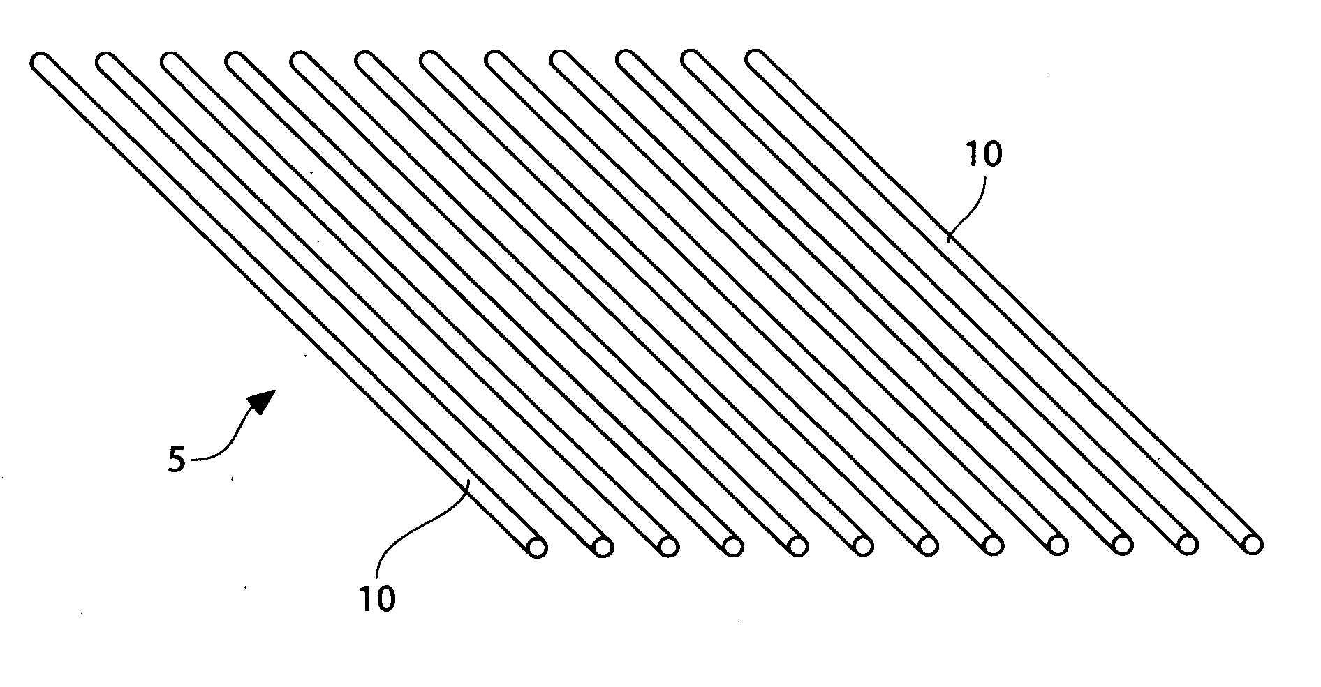
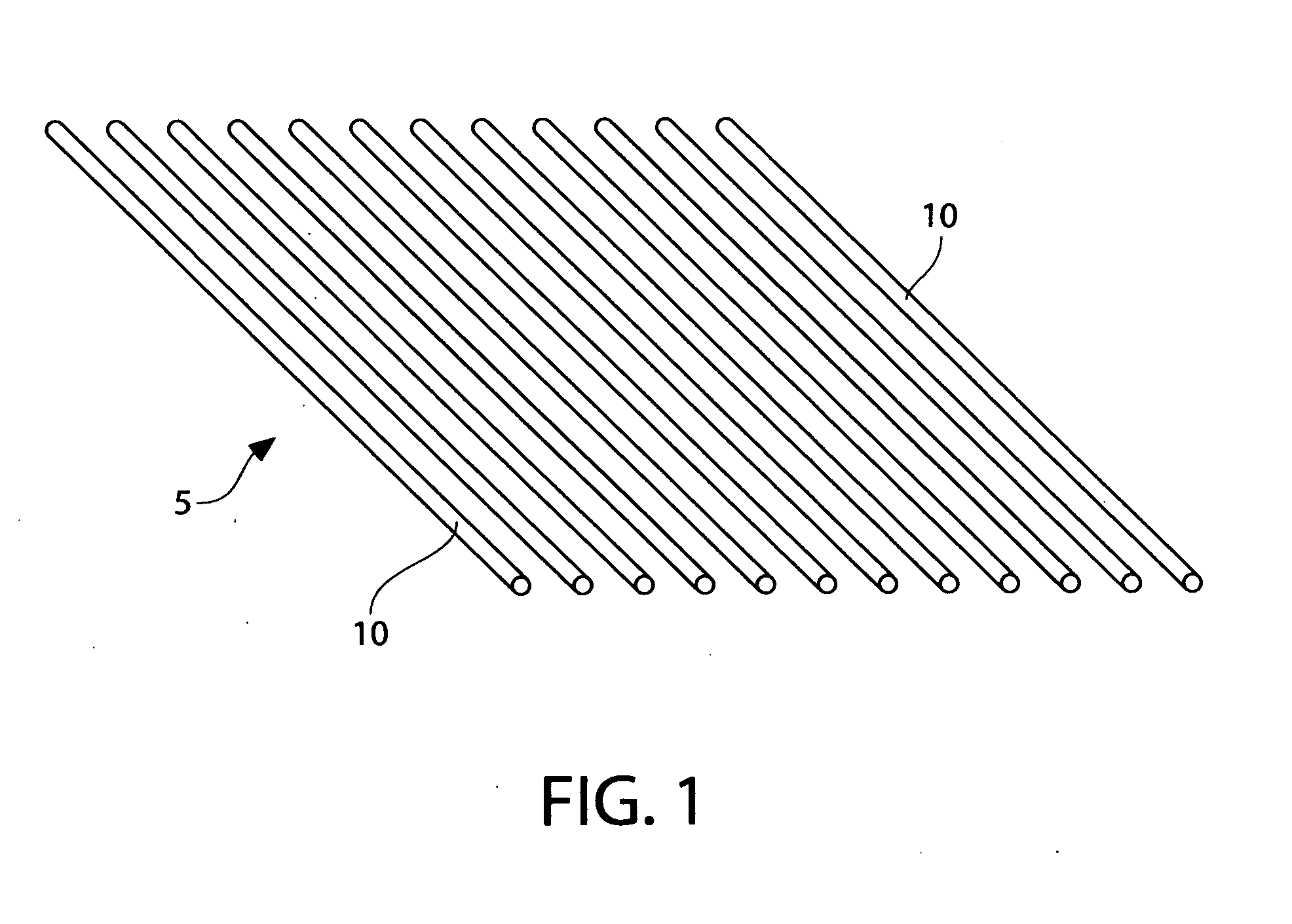
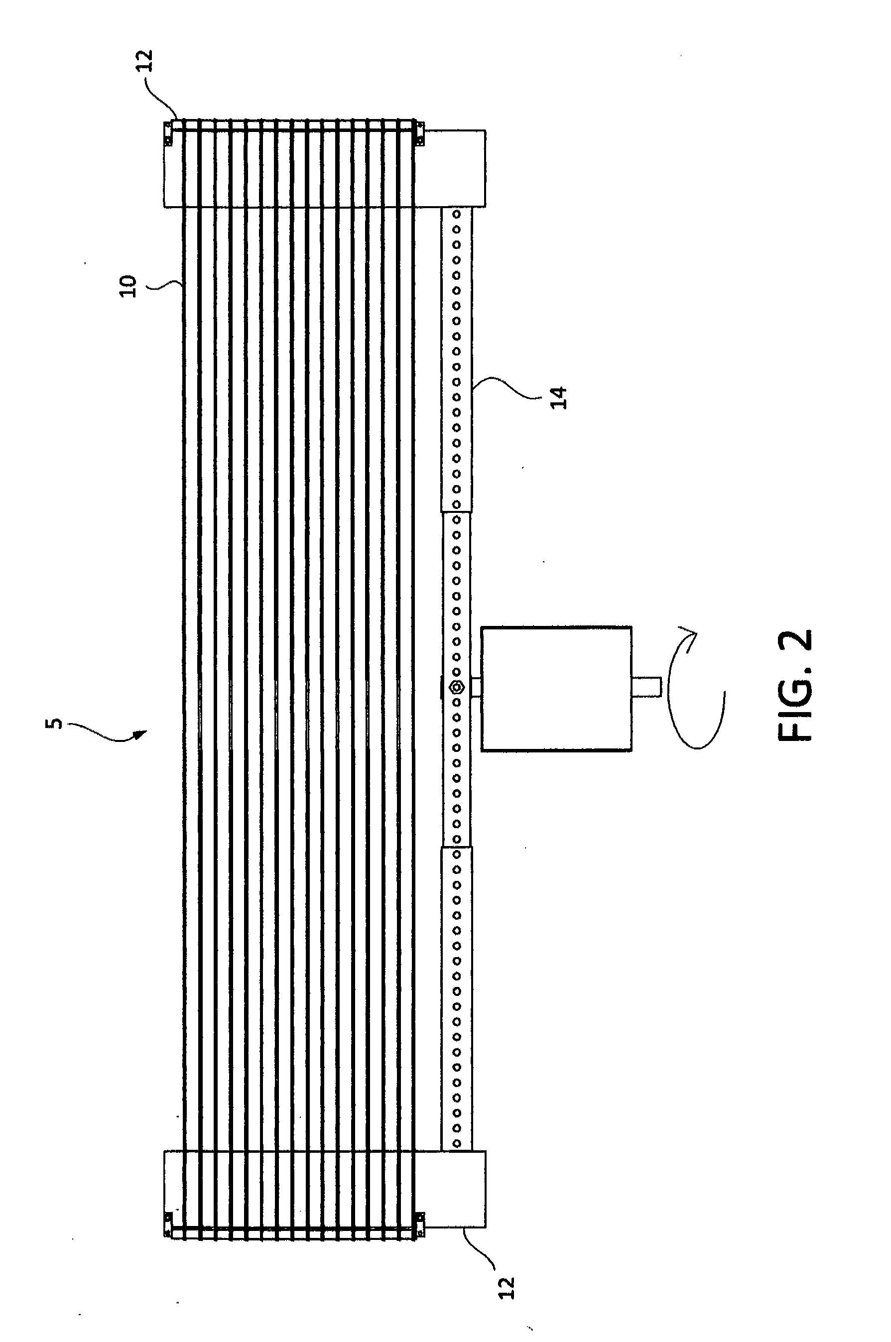
[0097]110 loops of a hollow fiber membrane prepared from polytetrafluoroethylene with an inner diameter of 1.5 mm and an outer diameter of 1.9 mm with a porosity of 40% were wrapped around a winding frame 400 mm from end to end and 250 mm wide. The winding frame was fitted with slotted rods at each end, with spacing between slots of 2.0 mm, ensuring spacing between the hollow fibers of 0.1 mm.

[0098]A potting film pre pared from Ethylene Fluorinated Ethylene Propylene copolymer (EFEP, Daikin RP 4020) with a thickness of 0.0762 mm, a width of 25.4 mm, and a length of 220 millimeters was woven between each individual fiber at the end of the winding frame. The film was passed underneath the first fiber on the frame and then alternately passed over the top of the next fiber and underneath the following fiber. This pattern was repeated until ...

example 2

[0105]In this example, the film potting method is used to produce a dead-end filter module. A continuous length of porous PTFE hollow fiber with the dimensions of 1.0 mm inner diameter and 1.5 mm outer diameter, with a specific gravity of 0.9 grams / cm3 was employed for this module. Using the winding apparatus previously described in Example 1, the fiber was wound between the two end pieces 120 times to create two 120-fiber webs on the top and bottom of the winding frame. The spacing between the fibers was maintained by machined grooves in the end pieces of the winding frame. The spacing between the fibers was set at 1.6 mm. The spacing between the two end elements of the frame was 610 mm. This process was repeated several times to generate sufficient fibers to make the unit.

[0106]A strip of 0.051 mm thick THV-220G film (Dyneon) with a width of 50 mm was woven in between the porous hollow fibers following previously described methodology at the two ends of the winding frame. After we...

example 3

[0113]In this example, the film potting method is used to produce a double ended cross flow module using double weaves. 200 loops of a hollow fiber membrane prepared from polytetrafluoroethylene with an inner diameter of 1.5 mm and an outer diameter of 1.9 mm with a porosity of 65% were wrapped around a winding frame 1000 mm from end to end and 400 mm wide, fitted with slotted rods at each end, with spacing between slots of 2.0 mm, ensuring spacing between the hollow fibers of 0.1 mm.

[0114]A potting tape prepared from Dyneon THV-220 with a thickness of 0.0762 mm, a width of 25.4 mm, and a length of 600 millimeters (referred to as the weave tape) was woven between each individual fiber at the end of the winding frame starting by passing under the first fiber, over the adjacent fiber, and continuing across the frame, resulting in a strip of potting film being interlaced between the fibers. The excess tape was trimmed off.

[0115]After completing the initial weaving step, a second piece ...


PUM

PropertyMeasurementUnit
melting pointaaaaaaaaaa
pressuresaaaaaaaaaa
temperaturesaaaaaaaaaa

Abstract

A hollow fiber membrane fluid transport device and its method of manufacture are disclosed wherein the fibers are comprised of Polytetrafluoroethylene (PTFE), and the potting materials are comprised of fluorocopolymer and or fluoroterpolymer based materials. The potting method described herein, utilizes a compressed chemically resistant fluorocopolymer and or fluoroterpolymer film, allows for ease of manufacture without destruction of the PTFE hollow fibers, with high packing densities, and without the processing complexity of pre-melting, extruding, or chemical crosslinking of any polymeric adhesives. Furthermore, the PTFE hollow fibers can be treated with a fluoropolymeric solvent solution before the chemically resistant film is applied to enhance the adhesion of the PTFE fiber to the film. PTFE hollow fibers, and its respective fluoro-co and terpolymers as potting films, impart high packing densities, superb chemical resistance and temperature resistance without membrane contamination, or low fiber pull strength, as is sometimes observed with standard potting materials such as polyurethane and epoxy.

Description

BACKGROUND Field[0001]This application relates to hollow fiber membrane fluid transport devices, specifically to the method of manufacturing such membrane fluid transport devices, and even more specifically to the means of assembling the hollow fibers into bundles and sealing the ends of the hollow fibers to make suitable contactors.BACKGROUND OF THE INVENTION[0002]Membrane contactors are useful devices for separation processes, contacting processes, or as filters. A membrane contactor consists of a membrane or membranes held in such a manner as to separate two regions of flow and enable the membrane to act as a separation means between the two phases, and a housing to enclose the membrane and contain and direct the flow of the multiple phases. The membrane acts as a barrier between the two fluid phases and selectively allows or prohibits the transport of one or more chemical species or particles from one fluid stream to the other. The housing has one or more ports to allow flow to ...

Claims


Application Information

Patent Timeline
Patent Type & Authority Applications(United States)
IPC IPC(8): B01D63/04B01D67/00B01D71/36B29C65/48B01D69/08
CPCB01D63/022Y10T156/1049B01D63/024B01D63/025B01D71/36B01D2315/08B29C65/68B29C66/0042B29L2031/14B29C66/53261B29K2995/0049B29C65/4815B29C65/5057B29C66/69B29C66/71B29C66/727B29C66/8122B29C66/81261B29C66/81471B29C65/02B01D63/023B01D2323/00B01D2319/04B01D69/02B29C65/5028B29L2031/602B01D63/02B01D63/021B29K2027/18B29K2827/12B29C65/10B29C66/1122B29C66/73161B29K2081/06B29K2079/08B29K2077/00B29K2071/00B29K2069/00B29K2027/12B29K2027/06
Inventor JERMAN, ROBERT EDWARDBROWN, JR., CORNELIUSHOBBS, KENNETH DONALDRUANO, CARLOSWOLANSKI, CHARLES EDWARD
Owner MARKEL CORPORATION
Why Eureka
Try Eureka