Three-area current differential protection method

A current differential and current technology, applied in the field of current differential protection and current differential protection of power systems, can solve the problem of low sensitivity of full current differential protection, and achieve the solution of sensitivity, safety, and good quickness. Effect

Active Publication Date: 2014-12-24
NARI TECH CO LTD
View PDF3 Cites 5 Cited by
  • Summary
  • Abstract
  • Description
  • Claims
  • Application Information

AI Technical Summary

Problems solved by technology

[0007] The purpose of the present invention is to provide a three-area current differential protection method in order to solve the problem of low sensitivity of the traditional full current differential protection

Method used


Image

  • Three-area current differential protection method
  • Three-area current differential protection method
  • Three-area current differential protection method

Examples


Embodiment Construction

[0037] The present invention will be described in further detail below with reference to the accompanying drawings and examples.

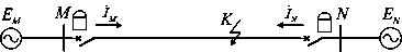
[0038] figure 1 is a schematic diagram of the application of the method of the present invention. Depend on figure 1 It can be seen that the protection is installed at the M-terminal and N-terminal bus outlets in the power system, and the current at both ends of the protected element is obtained by the protection device, that is, the double-terminal current with

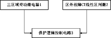
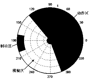
[0039] The basic process of the method of the present invention is to distinguish the area of ​​the relative relationship between the two-terminal currents on the amplitude-phase plane and the fault type, and then decide whether to operate or not according to the results of the two judgments. In order to realize the method of the present invention, can pass figure 2 The three-area differential relay 1, the criterion 2 of the linear zone of the fault CT outside the area and the pro...


PUM


Abstract

The invention provides a three-area current differential protection method, and belongs to the technical field of current differential protection in a power system. The area which the relative relationship of double-end currents belongs to on an amplitude-phase plane is judged, a fault type is judged, and whether protective actions are carried out or not is decided according to the judgment results. The amplitude and the phase of double-end currents are made full use of, the whole amplitude-phase plane is divided into three areas including a braking area, a fuzzy area and an action area, whether protective actions are carried out or not is determined according to the area where the relative relationship of the double-end currents is located, by means of an external fault CT linear area, high-resistance faults in the area and external fault CT saturation is judged in the fuzzy area, contradiction between sensitivity and safety is eliminated, and meanwhile, by means of the method, an external fault can be converted into a fault in the corresponding area quickly.

Description

technical field [0001] The invention belongs to the technical field of electric system current differential protection, more precisely, the invention relates to a current differential protection method which divides the amplitude and phase plane into three areas. Background technique [0002] Differential protection is one of the most widely used protections in power systems, and the reliability of its action has a significant impact on the safe and stable operation of the protected components. Especially in recent years, with the rapid development of the power system, it is required that the current differential protection can reflect the high-resistance fault in the zone and not malfunction when the CT saturation of the fault outside the zone, and the new protection principle has received more extensive attention and research. [0003] In the differential protection, it is necessary to consider the high-impedance fault in the zone and the CT saturation problem of the fault...

Claims


Application Information

Patent Timeline
Patent Type & Authority Applications(China)
IPC IPC(8): H02H7/26H02H3/26
CPCH02H3/26H02H7/26
Inventor 郑玉平路学刚吴通华
Owner NARI TECH CO LTD
Why Eureka
Try Eureka