
Brushless permanent magnet motor

A technology of permanent magnet motor and magnet group, which is applied in the direction of electrical components, electromechanical devices, etc.

Inactive Publication Date: 2014-12-24
DURQ MACHINERY
View PDF4 Cites 1 Cited by
  • Summary
  • Abstract
  • Description
  • Claims
  • Application Information

AI Technical Summary

Problems solved by technology

[0006] The main purpose of the present invention is to provide a brushless permanent magnet motor, which has a stable structure, can effectively reduce the instantaneous change of magnetic flux density and reduce the cogging torque and torque ripple, and greatly improve the problem of noise and vibration

Method used


Image

  • Brushless permanent magnet motor
  • Brushless permanent magnet motor
  • Brushless permanent magnet motor

Examples


Embodiment Construction

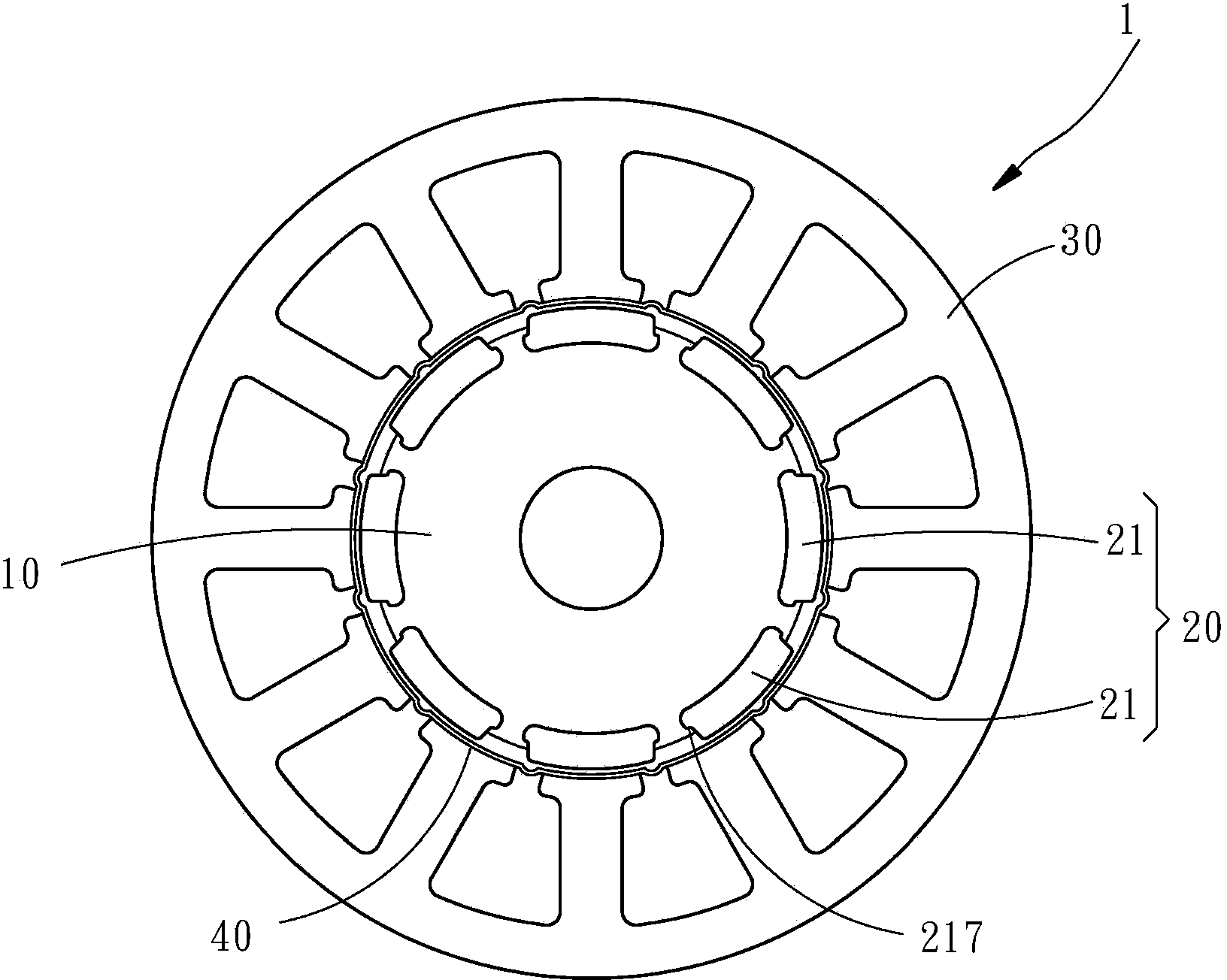
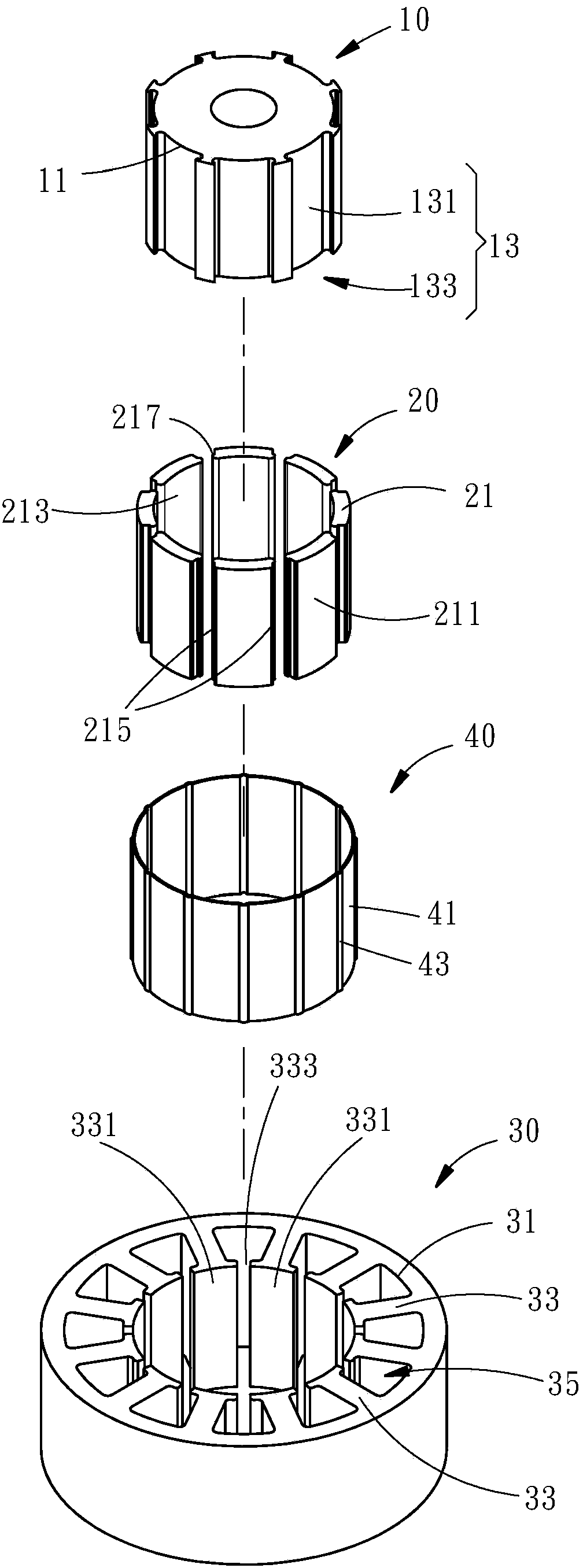
[0053] see figure 2 , image 3 and Image 6 Shown are the first and second preferred embodiments of the present invention. A brushless permanent magnet motor 1 , 2 includes a rotor 10 , a magnet assembly 20 , a stator 30 , and a sleeve 40 .

[0054]The rotor 10 includes an outer peripheral surface 11 and a plurality of slots 13 disposed along the outer peripheral surface 11 , and each of the slots 13 has a first accommodating space 131 sequentially from the rotor 10 toward the stator 30 And a second accommodating space 133 , the volume of the first accommodating space 131 is larger than that of the second accommodating space 133 .

[0055] The magnet group 20 is composed of a plurality of magnet units 21, each of the magnet units 21 has an outer arc surface 211, an inner arc surface 213 and two side surfaces 215, wherein each of the side surfaces 215 is adjacent to the inner arc surface 213 A flange 217 is provided for each of the magnet units 21 to be firmly embedded in t...


PUM


Abstract

The invention provides a brushless permanent magnet motor comprising a rotor, a magnet group nested on the rotor, a stator sleeved on the magnet group and coaxial with the rotor, and a sleeve barrel coaxial with the rotor and the stator and positioned between the magnet group and the stator; the stator comprises a plurality of tooth portions arranged along an inner periphery surface; one ends, far away from the inner periphery surface, of the tooth portions are respectively provided with a front end portion; a card stopping zone is formed along the front end portions; the sleeve barrel is provided with a plurality of card stopping portions respectively matched with positions of each card stopping zones; each card stopping portion is nested between the card stopping zones. The brushless permanent magnet motor is stable in structure, can effectively reduce magnetic flux density instant changes, can reduce cogging torque and ripples of the torque, and greatly reduces noise vibrations.

Description

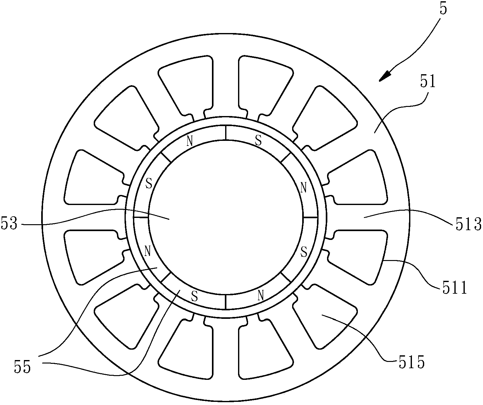
technical field [0001] The present invention relates to a brushless permanent magnet motor, in particular to a brushless permanent magnet motor with a sleeve structure. Torque ripple, and greatly improve the problem of noise and vibration. Background technique [0002] Compared with traditional motors, brushless permanent magnet motors have higher efficiency and torque density, and are therefore widely used in various drive systems, such as ship propellers, weeders, elevator tractors, etc. Most of the brushless permanent magnet motors on the market have the problem of large cogging torque. The reason is that the gap between the teeth of the stator is too large, which reduces the performance of the brushless permanent magnet motor, especially at low speeds. Yes, it will affect the normal operation of the brushless permanent magnet motor over time. [0003] In order to overcome the above-mentioned shortcomings, such as figure 1 As shown, the improved brushless permanent mag...

Claims


Application Information

Patent Timeline
Patent Type & Authority Applications(China)
IPC IPC(8): H02K29/03
Inventor 刘嘉盛郑义立
Owner DURQ MACHINERY
Learn More