Heuristic spanning method and system for link state routing

A free and node-based technology, applied in the transmission system, electrical components, wireless communication, etc., can solve the problems of not being able to generate trees, not taking into account the network status, and lack of information

Inactive Publication Date: 2014-12-24
MAXTECH COMM NETWORKS
4 Cites 2 Cited by

AI-Extracted Technical Summary

Problems solved by technology

Although only a few of these methods take into account the quality of communication between network nodes, none of these methods take into account the state of the entire network
This situation can cause considerable data loss du...

Abstract

A system and method for selecting at least one relay in a communication network; the network comprises a plurality of nodes; each of the nodes comprises at least one processing unit; each pair of the nodes is characterized by a first connection number; a first score is associated with each pair of (i) a first first connection number and (ii) a second first connection number; and each of the processing unit is programmed to execute the method.

Application Domain

TransmissionWireless communication

Technology Topic

Link-state routing protocolConnection number +2

Image

  • Heuristic spanning method and system for link state routing
  • Heuristic spanning method and system for link state routing
  • Heuristic spanning method and system for link state routing

Examples

  • Experimental program(1)

Example

[0107] Example 1
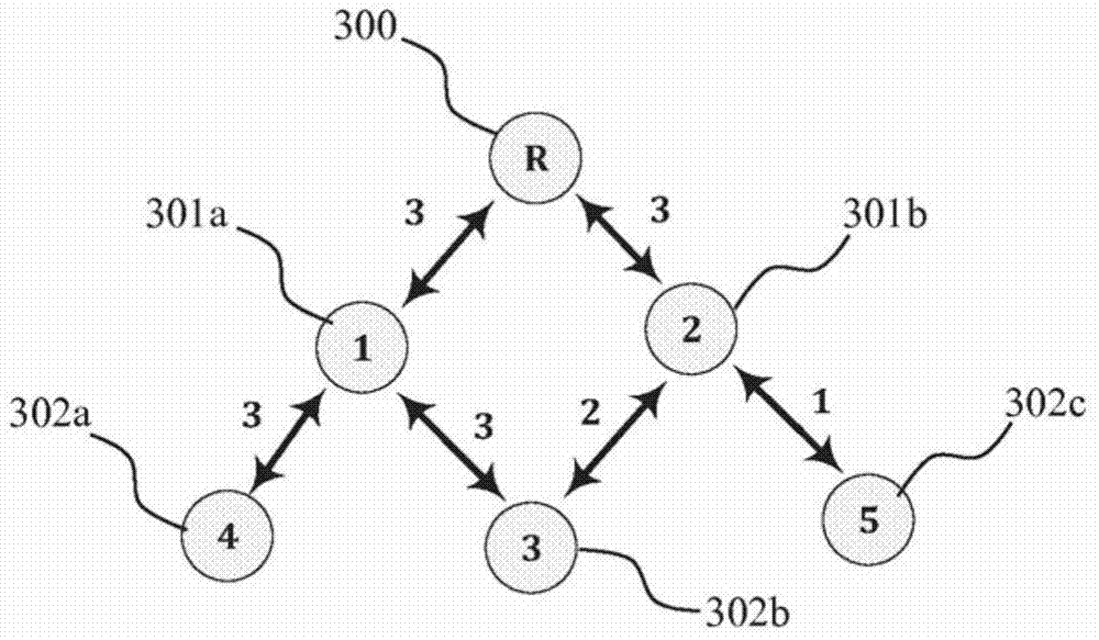
[0108] This example is provided in a non-limiting manner to illustrate a scope of the present invention, where in the method for selecting at least one relay in a communication network, the network includes a plurality of nodes; each of the nodes includes At least one processing unit; each pair of nodes in the node is represented by an integer between 0 and 3, where 0 means that the two nodes are not connected, and any number between 1 and 3 means the connection between the nodes and the connection strength. From image 3 It can be seen that the relay 300 is connected to two nodes with the first connection number 3 and the first connection number 3, namely the second node 1301a and the second node 2301b. The node 1301a is connected to a third node 4302a and a third node 3302b with a first connection number 3 and a first connection number 3. The node 2301b is connected to the third node 5302c and the third node 3302b with the first connection number 1 and the first connection number 2, respectively. The relay is not connected to the third node (ie, the third node 3302b, the third node 4302a, and the third node 5302c), therefore, the first connection number between the relay 300 and any third node is zero.
[0109] Given Figure 4b The first score of any two integers between 0 and 3 shown in the matrix 401, for example, given a score of 22 for {0, 3}, given a score of 0 for {3, 0}, and given The score of {1, 2} was 6. This score is used to assess the "desirability" of changing the strength of the connection between the two states; regarding the previous example, it is very "desirable" to change the connection from 0 to 3 (hence the acceptance level 22), and the level Changing from 3 to 0 is very "undesirable" (hence, acceptance level 0).
[0110] Now for each third node 302, the second connection number when the third node is connected via the second node 301 is given.
[0111] (i) When the third node 4302a is connected via the node 301a, the second connection number of the third node 4302a is 3, and when the third node 4302a is connected via the node 301b, the second connection number of the third node 4302a is 0;
[0112] (ii) When the third node 3302b is connected via the node 301a, the second connection number of the third node 3302b is 3, and when the third node 3302b is connected via the node 301b, the second connection number of the third node 3302b is 2;
[0113] (iii) When the third node 5302c is connected via the node 301a, the second connection number of the third node 5302c is 0, and when the third node 5302c is connected via the node 301b, the second connection number of the third node 5302c is 1;
[0114] Now given the first score of each third node 302 when the third node 302 is connected to each second node 301. The first score is based on changing the connection number between the relay 300 and the third node 302 from the first connection number (zero in this case) to the second connection number:
[0115] (i) According to the matrix 401, when the third node 4302a is connected via the second node 301a, the first score of the third node 4302a is 22, and when the third node 4302a is connected via the second node 301b, the third node 4302a's The first score is 0.
[0116] (ii) According to the matrix 401, when the third node 3302b is connected via the second node 301a, the first score of the third node 3302b is 22, and when the third node 3302b is connected via the second node 301b, the third node 3302b's The first score is 15.
[0117] (iii) According to the matrix 401, when the third node 5302c is connected via the second node 301a, the first score of the third node 5302c is 0, and when the third node 5302c is connected via the second node 301b, the third node 5302c The first score is 8.
[0118] Now according to the first score of the third node 302, the second scores of the second node 301a and the second node 301b are given:
[0119] (i) The second score of the second node 301a is the sum of the first scores of the third node 302 when the third node 302 is connected via the second node 301a: 22+22+0=44;
[0120] (ii) The second score of the second node 301b is the sum of the first scores of the third node 302 when the third node 302 is connected via the second node 301a: 0+15+8=23.

PUM

no PUM

Description & Claims & Application Information

We can also present the details of the Description, Claims and Application information to help users get a comprehensive understanding of the technical details of the patent, such as background art, summary of invention, brief description of drawings, description of embodiments, and other original content. On the other hand, users can also determine the specific scope of protection of the technology through the list of claims; as well as understand the changes in the life cycle of the technology with the presentation of the patent timeline. Login to view more.
Why Eureka
Try Eureka