Simulation touch type pulse sensing device and pulse collecting method

A sensing device and touch-type technology, applied in catheters and other directions, can solve the problems of low accuracy of results and failure to collect pulse signals, etc., and achieve the effect of improving accuracy

Active Publication Date: 2014-12-31
HARBIN HUAYU MEDICAL ELECTRONICS INSTR
View PDF7 Cites 12 Cited by
  • Summary
  • Abstract
  • Description
  • Claims
  • Application Information

AI Technical Summary

Problems solved by technology

[0004] The present invention is to solve the problem that the result obtained by the existing pulse condition diagnosis method is low in accuracy, and the existing pulse condition sensor cann...

Method used


Image

  • Simulation touch type pulse sensing device and pulse collecting method
  • Simulation touch type pulse sensing device and pulse collecting method
  • Simulation touch type pulse sensing device and pulse collecting method

Examples


specific Embodiment approach 1

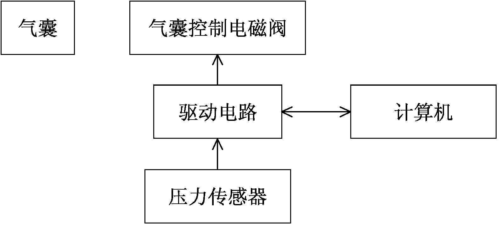
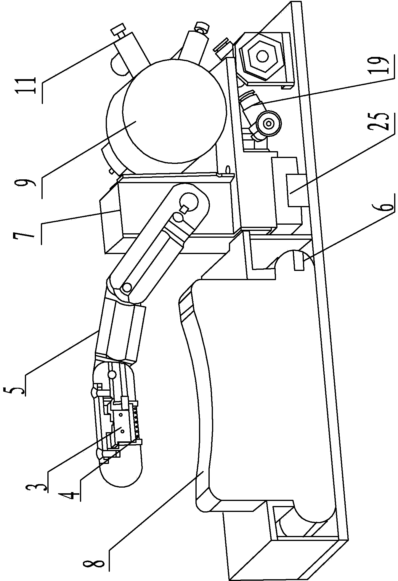
[0026] Specific embodiment one: reference figure 1 , image 3 , Figure 4 , Figure 5 with Image 6 Detailed description of this embodiment, the simulated touch pulse sensor device described in this embodiment includes: a drive circuit 1, an air bag control solenoid valve 2, a pressure sensor 3, a pulse sensor 4, an artificial finger 5, an inflation port 6, a bracket 7 and airbag 8;

[0027] The airbag control drive signal output terminal of the drive circuit 1 is connected to the signal input terminal of the airbag control solenoid valve 2, and the pressure signal output terminal of the pressure sensor 3 is connected to the pressure signal input terminal of the drive circuit 1;

[0028] The base of the artificial finger 5 is fixed on the bracket 7, and a pulse sensor fixing frame is fixed at the lower end of the artificial finger 5, and the bottom of the fixing frame protrudes from the lower surface of the artificial finger 5, and the pulse sensor 4 is fixed in the fixing frame;

...

specific Embodiment approach 2

[0034] Embodiment 2: This embodiment is a further description of the simulated touch pulse condition sensing device described in Embodiment 1. In this embodiment, it also includes: a computer;

[0035] The control signal output terminal of the computer is connected to the control signal input terminal of the drive circuit 1, and the pulse signal output terminal of the pulse sensor 4 is connected to the pulse signal input terminal of the computer.

[0036] The simulated touch pulse condition sensing device described in this embodiment adds a computer as a controller to control the action of the driving circuit. At the same time, the computer can also be used as a storage module to save the pulse information stored in the pulse sensor.

[0037] The artificial touch pulse condition sensing device described in this embodiment can also add an isolation circuit;

[0038] The control signal output terminal of the computer is connected to the control signal input terminal of the isolation cir...

specific Embodiment approach 3

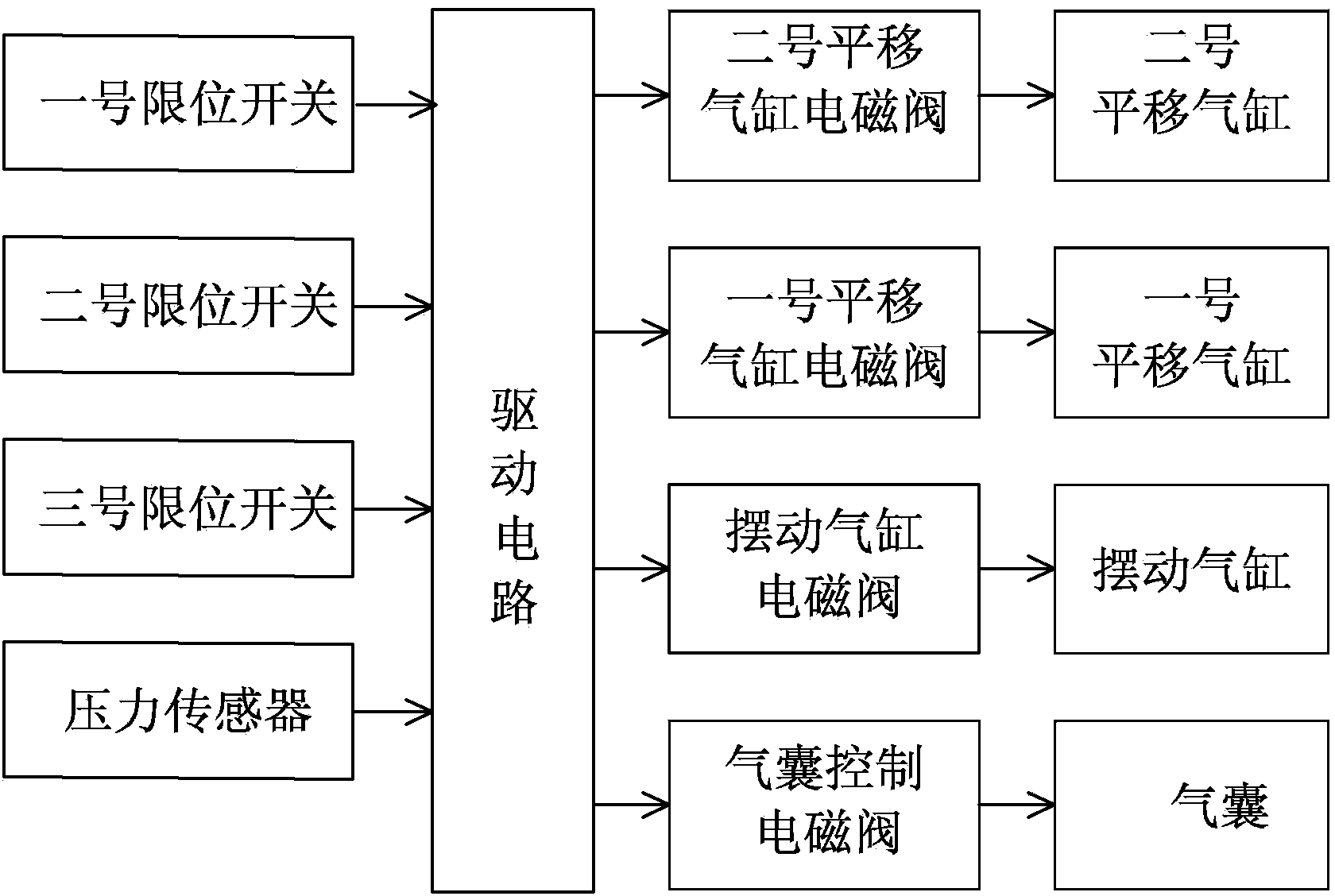
[0041] Specific embodiment three: reference figure 2 , image 3 , Figure 4 , Figure 5 with Image 6 Detailed description of this embodiment, this embodiment is a further description of the simulated touch pulse sensor device described in the first embodiment. In this embodiment, it also includes: a swing cylinder 9, a swing cylinder solenoid valve 10, and a swing cylinder Inflating port 11 and transmission components;

[0042] The root of the artificial finger 5 is fixed on the bracket 7 through the transmission assembly;

[0043] The swing cylinder 9 is used to drive the transmission assembly to drive the artificial finger 5 to swing up and down with the root of the finger as the axis;

[0044] The air inlet of the swing cylinder 9 is connected to the swing cylinder charge port 11. The swing cylinder solenoid valve 10 is provided on the air path between the swing cylinder 9 and the swing cylinder charge port 11, and the swing cylinder solenoid valve drive signal output terminal ...


PUM


Abstract

The invention relates to a simulation touch type pulse sensing device and a pulse collecting method, belongs to the field of medical apparatus and instruments, and solves the problems that results acquired by existing pulse diagnosing methods are low in precision, and existing pulse sensors cannot collect pulse signals according to pulse feeling environments. The simulation touch type pulse sensing device and the pulse collecting method are characterized in that an air bag is inflated by an external air pump to change the pressure between the hand of a person and a pulse sensor, the pressure is then collected through a pressure sensor, and different pulse feeling environments are achieved, that is to say, different pressure environments of light, middle and heavy pressure applied by the fingers during manual pulse feeling are simulated. Compared with the existing pulse sensors, the simulation touch type pulse sensing device and the pulse collecting method have the advantages that precision is increased by 15%, and the device and the method are suitable for providing precise pulse data for doctors during pulse feeling of traditional Chinese medicine.

Description

Technical field [0001] The invention belongs to the field of medical equipment, and particularly relates to a pulse condition acquisition method of a pulse condition sensor device. Background technique [0002] Pulse diagnosis is one of the four diagnosis of Chinese medicine, and it occupies a very important position in Chinese medicine diagnosis. The usual practice of pulse diagnosis in traditional Chinese medicine is that Chinese physicians use their fingers to touch the three parts of the patient’s radial artery at the Cunkou, Guan, and Ulnar, and apply different pressures such as floating, middle, and sinking to feel the changes in the patient’s pulse wave. Corresponding to floating, neutral, sinking and other pressures, a series of pulse waves containing information such as pulse ups and downs, strength, trend, shape, width, and rhythm, are called pulse conditions. From the pulse information, the doctor can understand the patient's case status. However, this kind of tradit...

Claims


Application Information

Patent Timeline
IPC IPC(8): A61B5/02
Inventor 梁喜才方滨华李永光刘博峰张文娟
Owner HARBIN HUAYU MEDICAL ELECTRONICS INSTR
Why Eureka
Try Eureka