Deburring device including visual sensor and force sensor

A vision sensor, burr removal technology, applied in instruments, manufacturing tools, metal processing equipment, etc., can solve the problems of inability to obtain sufficient burr removal accuracy, increased cost, and difficulty in improving burr removal accuracy.

Active Publication Date: 2014-12-31
FANUC LTD
View PDF8 Cites 71 Cited by
  • Summary
  • Abstract
  • Description
  • Claims
  • Application Information

AI Technical Summary

Problems solved by technology

[0006] In the technology disclosed in JP-A-8-141881, in the case where the detection information of the visual sensor contains non-negligible errors, it is possible that an excessive force acts on the deburring tool during the processing and the processing surface may be damaged. the quality becomes uneven
[0007] In the technique disclosed in JP-A-7-266269, much time is required to instruct the robot path, so sufficient efficiency cannot be obtained resulting in cost increase
[0008] In the technique disclosed in JP-A-7-308879, in the case where there are individual differences between the workpiece model and the actual workpiece, there is a possibility that sufficient accuracy of burr removal cannot be obtained
[0009] In the technique disclosed in JP-A-2012-020348, there is a possibility that sufficient accuracy of burr removal cannot be obtained in the case where there is a non-negligible point of difference in shape between the design data and the actual workpiece
Especially when it is desired to remove burrs from casting workpieces, it is difficult to improve the accuracy of deburring because the deviation from the design data varies greatly depending on the individual differences of the workpieces

Method used


Image

  • Deburring device including visual sensor and force sensor
  • Deburring device including visual sensor and force sensor
  • Deburring device including visual sensor and force sensor

Examples


Embodiment Construction

[0044] Hereinafter, embodiments of the present invention will be described with reference to the attached drawings. In the illustrated embodiment, please note that the scales of the constituent elements are appropriately changed to facilitate understanding of the present invention. In the description of different embodiments, the same reference numerals are used for the same or corresponding structural elements, and overlapping descriptions are appropriately omitted.

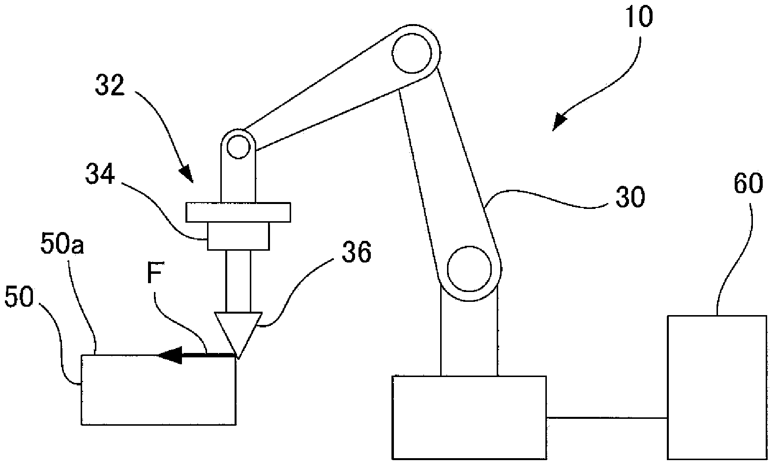
[0045] figure 1 It is a schematic diagram showing the configuration of the deburring device 10 according to the first embodiment of the present invention. The deburring device 10 includes: a articulated robot 30 having a plurality of arms; a force sensor 34 attached to a wrist 32 located at the front end of the arm of the robot 30; a deburring tool 36 attached to the force sensor 34; The control device 60 controls the robot 30 .

[0046] The robot 30 can take various positions and postures by rotating unillus...


PUM


Abstract

A deburring device includes a deburring tool for removing burrs from an object, a robot for moving an object or the tool, a force sensor for detecting force acting on the tool, and a visual sensor for detecting a position of a burr portion of the object. According to the deburring device, information regarding shape data of the burr portion and a posture of the tool is obtained beforehand based on three-dimensional data of the object. Based on the shape data and the posture of the tool, a robot program is created. In accordance with an actual burr portion detected by the visual sensor, the robot program is replaced as necessary. During the deburring, the robot is controlled according to the force control by using a detected value from the force sensor.

Description

technical field [0001] The present invention relates to a deburring device for removing burrs formed on workpieces. Background technique [0002] There is known a deburring device that removes burrs formed at a plane boundary portion when a workpiece is plane-machined. In the deburring device and method disclosed in JP-A-8-141881, the target workpiece is determined based on measurement data obtained by a three-dimensional shape measuring device and prestored relationship data representing the surface shape of the workpiece and the constraining surface of the workpiece The position of the constraining surface of the workpiece, and the position of the intersection line between the planar part of the workpiece surface and the constraining surface of the workpiece is determined as the deburring path. [0003] In JP-A-7-266269, it is disclosed that, in a deburring method using a robot body having a tool and a force sensor, after performing rough indication in the indication stag...

Claims


Application Information

Patent Timeline
Patent Type & Authority Applications(China)
IPC IPC(8): B23D79/00B25J9/16B25J13/08
CPCB24B49/16B24B9/00B24B27/0038B24B49/12B25J9/1633B25J9/1697B25J11/006G05B2219/37208G05B2219/45151
Inventor 顾义华
Owner FANUC LTD
Why Eureka
Try Eureka