System and method for enhancing computer-generated images of terrain on aircraft displays

a computer-generated image and aircraft display technology, applied in the field of display systems, can solve the problems of significant non-intuitive imaging problems, significant data integrity issues, and similar issues may arise in other applications, and achieve the effects of rapid initialization of data, and enhancing the visibility of terrain

Active Publication Date: 2007-01-04
HONEYWELL INT INC
View PDF12 Cites 101 Cited by
  • Summary
  • Abstract
  • Description
  • Claims
  • Application Information

AI Technical Summary

Benefits of technology

[0006] The present invention provides an improved system and method for enhancing the visibility of terrain and navigation information on aircraft displays, such as, for example, continuous, three-dimensional perspective view aircraft displays conformal to the visual environment. In accordance with a preferred embodiment of the present invention, an aircraft display system is provided that includes a processing unit, a navigation system, a database for storing high resolution terrain data, a graphics display generator, and a visual display. One or more independent, higher precision databases with localized position data, such as navigation data or position data is onboard. One or more onboard vision sensor systems associated with the navigation system provide real-time spatial position data for display. One or more data links is available to receive precision spatial position data from ground-based stations. The processing unit directs the graphics display generator to generate graphic control signals for the visual display, which enhance the visibility of the terrain and navigational information shown on the continuous, three-dimensional perspective view display. Essentially, before terrain and navigational objects (e.g., runways) are displayed, a real-time correction and augmentation of the terrain data is performed for those regions that are relevant and / or critical to flight operations, in order to ensure that the correct terrain data is displayed with the highest possible integrity. These corrections and augmentations performed are based upon higher precision, but localized onboard data, such as navigational object data, sensor data, or up-linked data from ground stations. Whenever discrepancies exist, terrain data having a lower integrity can be corrected in real-time using data from a source having higher integrity data. A predictive data loading approach is used to allow such real-time operations, whereby the processing unit determines an aircraft's current position, heading and speed, and initially loads a patch of terrain data for a region that is suitably sized to provide a rapid initialization of the data, data corrections, and for a reasonable amount of flight time. The processing unit then monitors the aircraft's position, heading and speed, and continuously predicts the potential boundaries of a three-dimensional region or volume of terrain in the flight path based on the aircraft's position, heading and speed. The processing unit compares the predicted boundaries with the boundaries of the initially loaded terrain data, and if the distance from the aircraft to a predicted boundary is determined to be less than a predetermined value (e.g., associated with the boundaries of the initially loaded data), then the processing unit loads a new patch of terrain data that is optimally sized given the aircraft's current position, heading and speed. In order to minimize the duration of the pre-processing operation prior to loading the new patch of terrain data, the processing unit compiles the new patch of terrain data partially with old data derived from the previously loaded patch and also new data retrieved from the database.

Problems solved by technology

However, a major drawback of this approach is that significant data integrity issues exist with the computer-generated terrain information derived from the onboard databases, and significant non-intuitive imaging issues exist with the real-time terrain information derived from the vision sensor systems.
Also, similar issues may arise in other applications.
For example, data integrity and imaging issues can arise with the use of synthetic vision displays for Unmanned Aerial Vehicle (UAV) operations, and high-fidelity flight training simulators using flight worthy data sources where certain targets or objects are mapped with higher accuracy than the underlying terrain.
As a result of these problems, visual display disparities and operator errors can occur.
However, since terrain data for aircraft applications typically covers the entire globe on a continuous basis, such an onboard database would contain an enormous amount of terrain data.
Thus, it would be an almost impossible task to physically verify all of the data points in such a database for critical flight applications.
Another significant problem with the use of high resolution terrain data for these perspective view display applications is that they place a heavy load on the processor involved, and therefore, certain data computation techniques (e.g., simple- or continuous-level of detail computation techniques) have to be used in order to reduce the computational workload.
Consequently, using the existing data computation techniques, whenever a large patch of terrain data is loaded for pre-processing during the initialization phase (e.g., immediately after the terrain display application is turned on), the processing system experiences a significant latency period and a corresponding delay before that data can be displayed.
Similarly, using existing data computation techniques, if the processing system attempts to load such terrain data in real-time, then significant discontinuities and instabilities can occur with the display of the data derived from regions close to the borders of previously loaded data.
As such, these data integrity and processing problems impose significant data storage and processing limitations on existing onboard aircraft display systems, which significantly limit the usefulness of displays for flight critical applications.
As such, this loss of visual contact of such critical runway / terrain information by a pilot (e.g., especially in the vicinity of that airport) decreases the effectiveness, accuracy and safety of the flight decisions being made, and thus increases the possibility that dangerous flight management, navigation or control errors can occur.

Method used


Image

  • System and method for enhancing computer-generated images of terrain on aircraft displays
  • System and method for enhancing computer-generated images of terrain on aircraft displays
  • System and method for enhancing computer-generated images of terrain on aircraft displays

Examples


Embodiment Construction

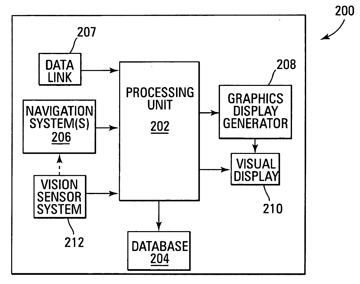
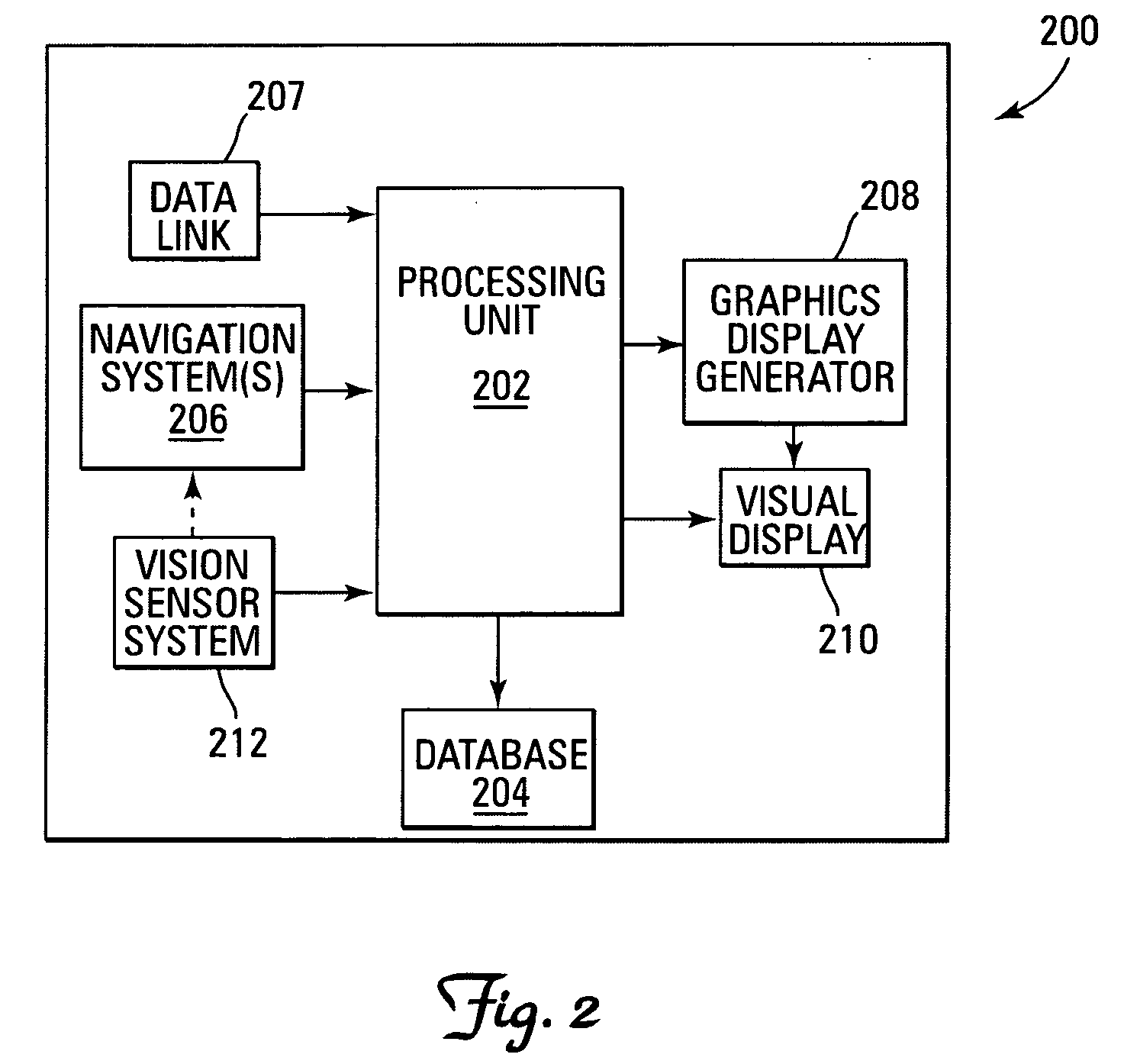
[0015] With reference again to the figures, FIG. 2 depicts a block diagram of an example system 200 for ensuring the correctness of terrain information on an aircraft display (e.g., continuous, three-dimensional perspective view display), which can be used to implement a preferred embodiment of the present invention. For this example, system 200 includes a processing unit 202, a database 204, a navigation system 206, a high speed data link 207, a graphics display generator 208, a visual display 210, and one or more vision sensor systems 212. Notably, it should be understood that although system 200 appears in FIG. 2 to be arranged as an integrated system, the present invention is not intended to be so limited and can also include an arrangement whereby one or more of processing unit 202, database 204, navigation system 206, data link 207, graphics display generator 208, visual display 210 and one or more vision sensor systems 212 is a separate component or a subcomponent of another ...


PUM


Abstract

A system and method are disclosed for enhancing the visibility and ensuring the correctness of terrain and navigation information on aircraft displays, such as, for example, continuous, three-dimensional perspective view aircraft displays conformal to the visual environment. More specifically, an aircraft display system is disclosed that includes a processing unit, a navigation system, a database for storing high resolution terrain data, a graphics display generator, and a visual display. One or more independent, higher precision databases with localized position data, such as navigation data or position data is onboard. Also, one or more onboard vision sensor systems associated with the navigation system provides real-time spatial position data for display, and one or more data links is available to receive precision spatial position data from ground-based stations. Essentially, before terrain and navigational objects (e.g., runways) are displayed, a real-time correction and augmentation of the terrain data is performed for those regions that are relevant and/or critical to flight operations, in order to ensure that the correct terrain data is displayed with the highest possible integrity. These corrections and augmentations performed are based upon higher precision, but localized onboard data, such as navigational object data, sensor data, or up-linked data from ground stations. Whenever discrepancies exist, terrain data having a lower integrity can be corrected in real-time using data from a source having higher integrity data. A predictive data loading approach is used, which substantially reduces computational workload and thus enables the processing unit to perform such augmentation and correction operations in real-time.

Description

FIELD OF THE INVENTION [0001] The present invention relates generally to the field of display systems, and more specifically, but not exclusively, to a system and method for enhancing computer-generated images of terrain on aircraft displays. BACKGROUND OF THE INVENTION [0002] Modern aircraft contain visual display systems that provide flight crews with substantial amounts of important operational and situational awareness information about the environment outside the aircraft, such as terrain. In fact, multi-functional aircraft displays that provide flight crews with computer-enhanced, three-dimensional perspective images of terrain (e.g., especially during conditions of low visibility) are known. One approach used to enhance terrain imagery in existing multi-functional aircraft displays is to combine high resolution, computer-generated terrain image data derived from onboard databases (e.g., synthetic vision systems) with enhanced, real-time terrain image data derived from onboard...

Claims


Application Information

Patent Timeline
Patent Type & Authority Applications(United States)
IPC IPC(8): G06G7/70G06F19/00
CPCG01C23/00
Inventor HE, GANG
Owner HONEYWELL INT INC
Why Eureka
Try Eureka