Conveying device for channel crossing

A technology for conveying devices and pathways, which is applied in transportation and packaging, railway car body parts, railway vehicles, etc., and can solve problems such as uneven ground, difficulty in moving smooth passage parts, and operator tripping

Active Publication Date: 2017-11-03
NAKANISHI METAL WORKS CO LTD
View PDF1 Cites 0 Cited by
  • Summary
  • Abstract
  • Description
  • Claims
  • Application Information

AI Technical Summary

Problems solved by technology

[0006] However, in the conveying device like Patent Document 1, in its structure, it is necessary to pave the left and right sides for guiding the wheels (14, 15) and the auxiliary guided body (17) to the above-mentioned crossing line (sub-path portion 8C, 8C). A pair of secondary guides (5, 5) (referring to Patent Document 1 Figure 5 as well as Image 6 ), therefore, in the passage (7) along the above-mentioned conveying line, when the above-mentioned conveying trolley does not pass through, the part for the above-mentioned vehicles and operators to cross and pass, that is, the ground of the above-mentioned crossing line is not flat, on the above-mentioned ground presence of orbital protrusions
[0007] Therefore, it is necessary for the vehicle to get over the protrusion, so when passing over the protrusion, it may be difficult to pass smoothly, parts, etc. may move due to vibration, and the operator may trip over the protrusion.

Method used


Image

  • Conveying device for channel crossing
  • Conveying device for channel crossing
  • Conveying device for channel crossing

Examples


Embodiment approach 1

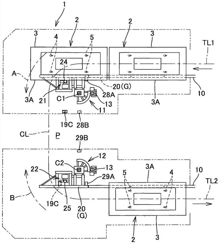
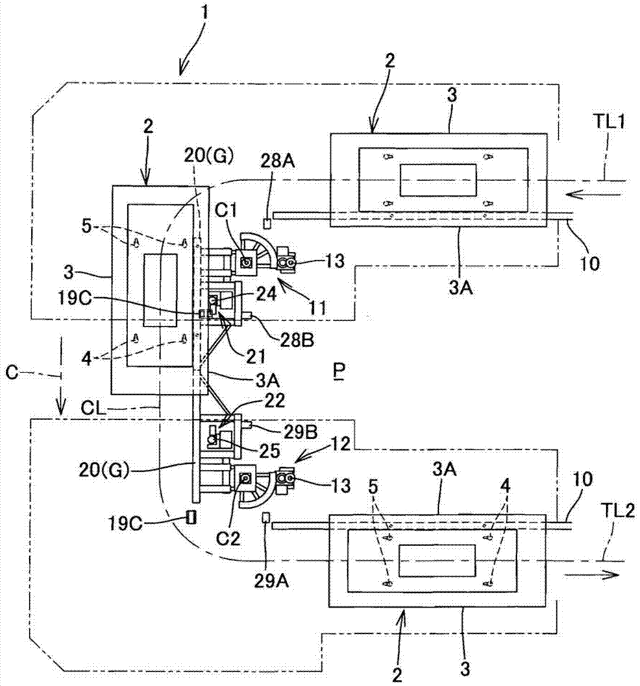
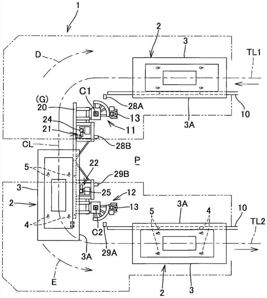
[0075] Such as Figure 1 to Figure 4 As shown in the schematic plan view of , the conveying device 1 according to Embodiment 1 of the present invention is formed to include parallel conveying lines (the first conveying line TL1 as the outgoing line and the first transporting line TL1 as the returning line The crossing line CL that moves the transport trolley 2 carrying the objects along the horizontal direction perpendicular to the transport lines TL1 and TL2 between the second transport lines TL2) is located on the parallel first transport line TL1 and the second transport line TL1. The crossing line CL is traversed between the transmission lines TL2 and along the path P of the transmission lines TL1, TL2.

[0076] The relatively large transport trolley 2 provided with the base 3 is equipped with left and right front wheels 4, 4 and rear wheels 5, 5 at the front and rear. Free swivel wheels (swivel casters, free casters). In addition, only one of the front wheels 4, 4 and t...

Embodiment approach 2

[0096] Such as Figure 10 As shown in the schematic plan view of , the transportation device 1 according to Embodiment 2 of the present invention has a long distance between the parallel transportation lines TL1 and TL2 (the length of the crossing line CL) so as to traverse the crossing line CL. There are two parallel passages P1, P2 formed in the way. In addition, such parallel passages may be three or more.

[0097] On the crossing line CL, a fixed guide rail 30 connected to the movable guide rails 20 and 20 of the first trolley rotating device 11 and the second trolley rotating device 12 is provided between the passages P1 and P2, and a passageway platform is provided. The vehicle conveyance devices 23, 23 and other devices are the same as those in the first embodiment.

[0098] Here, the trolley conveying devices 23 and 23 between the passages are friction drive devices, and the friction rollers 26 and 27 are brought into contact with the rubbed surface 3A of the base 3 ...


PUM


Abstract

A conveying device (1) for passage crossing, comprising a crossing line for handing over trolleys (2) between parallel conveying lines, the passage between the conveying lines traverses the crossing line, and the trolley (2) Equipped with freely rotatable wheels (4, 5), the conveying device (1) is equipped with: a first trolley turning device (11) for turning the trolley (2) from the conveying line to the crossing line; The second trolley turning device that rotates; and the platform that transports the trolley (2) on the crossing line under the state that the first trolley turning device (11) and the second trolley turning device are rotated along the crossing line Vehicle driving device; the first trolley turning device (11) and the second trolley turning device face each other across the passage in such a way that the center of rotation is located on the side of the passage than the center of the conveying line, and the first trolley turning device (11) ) and the rotating device of the second trolley do not have a part that invades the passage in the state along the conveying line.

Description

technical field [0001] The present invention relates to a conveying device having a function of handing over conveying trolleys between parallel conveying lines. More specifically, the present invention relates to a tractor for parts supply, which can use a crossing line capable of moving a trolley between the parallel conveying lines, Conveyor for the passage of workers etc. Background technique [0002] There is a conveying device that is formed so that, between parallel conveying lines (outgoing and returning lines) for conveying objects to be conveyed, the edge of a conveyance trolley on which the objects to be conveyed is mounted is perpendicular to the conveying path. The crossing line moving in the horizontal direction is located between the above-mentioned parallel conveying lines and crosses the above-mentioned crossing line along the path of the above-mentioned conveying line (for example, refer to Patent Document 1). [0003] The conveying device of Patent Docume...

Claims


Application Information

Patent Timeline
Patent Type & Authority Patents(China)
IPC IPC(8): B61J1/02B61B13/12
Inventor 北口亮一
Owner NAKANISHI METAL WORKS CO LTD
Why Eureka
Try Eureka